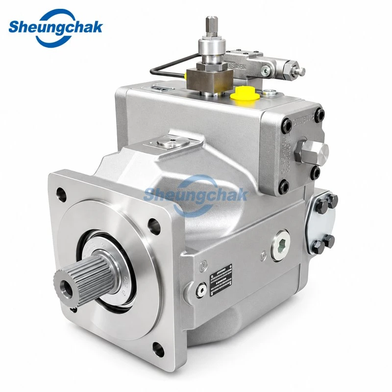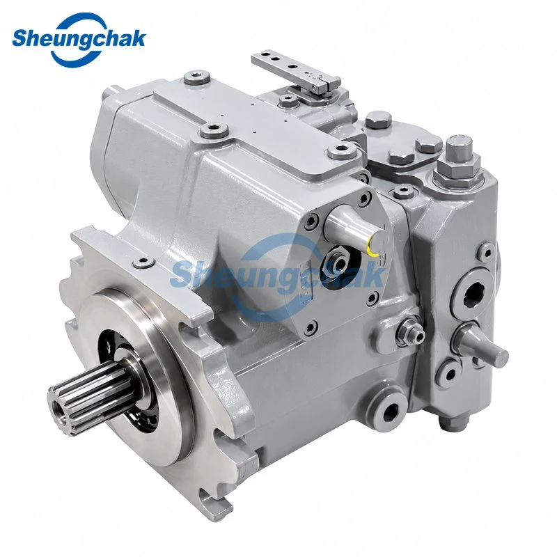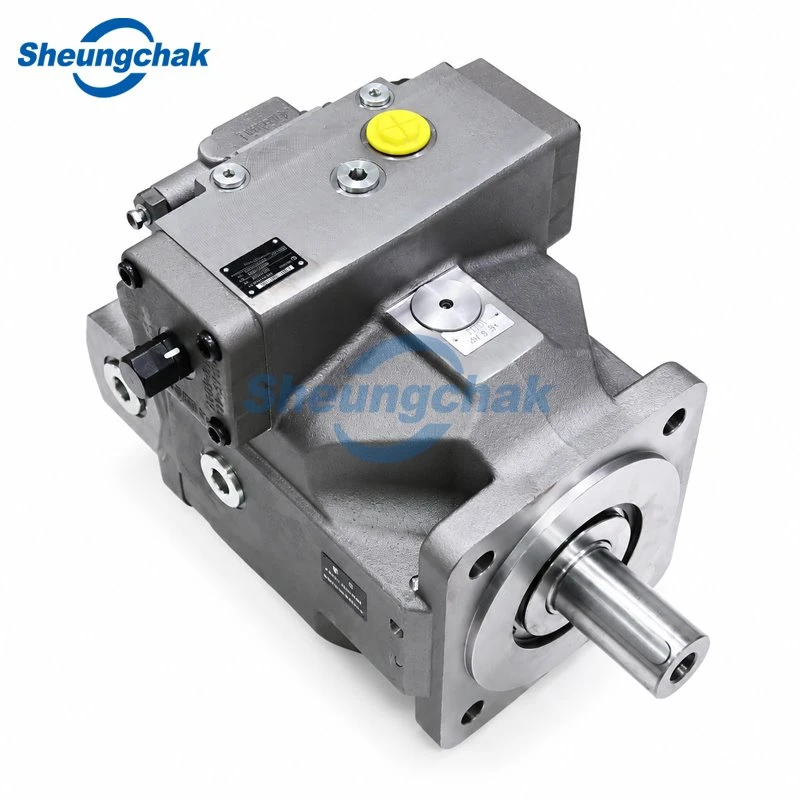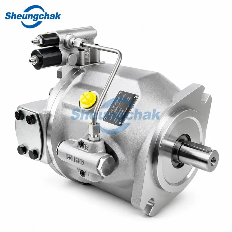

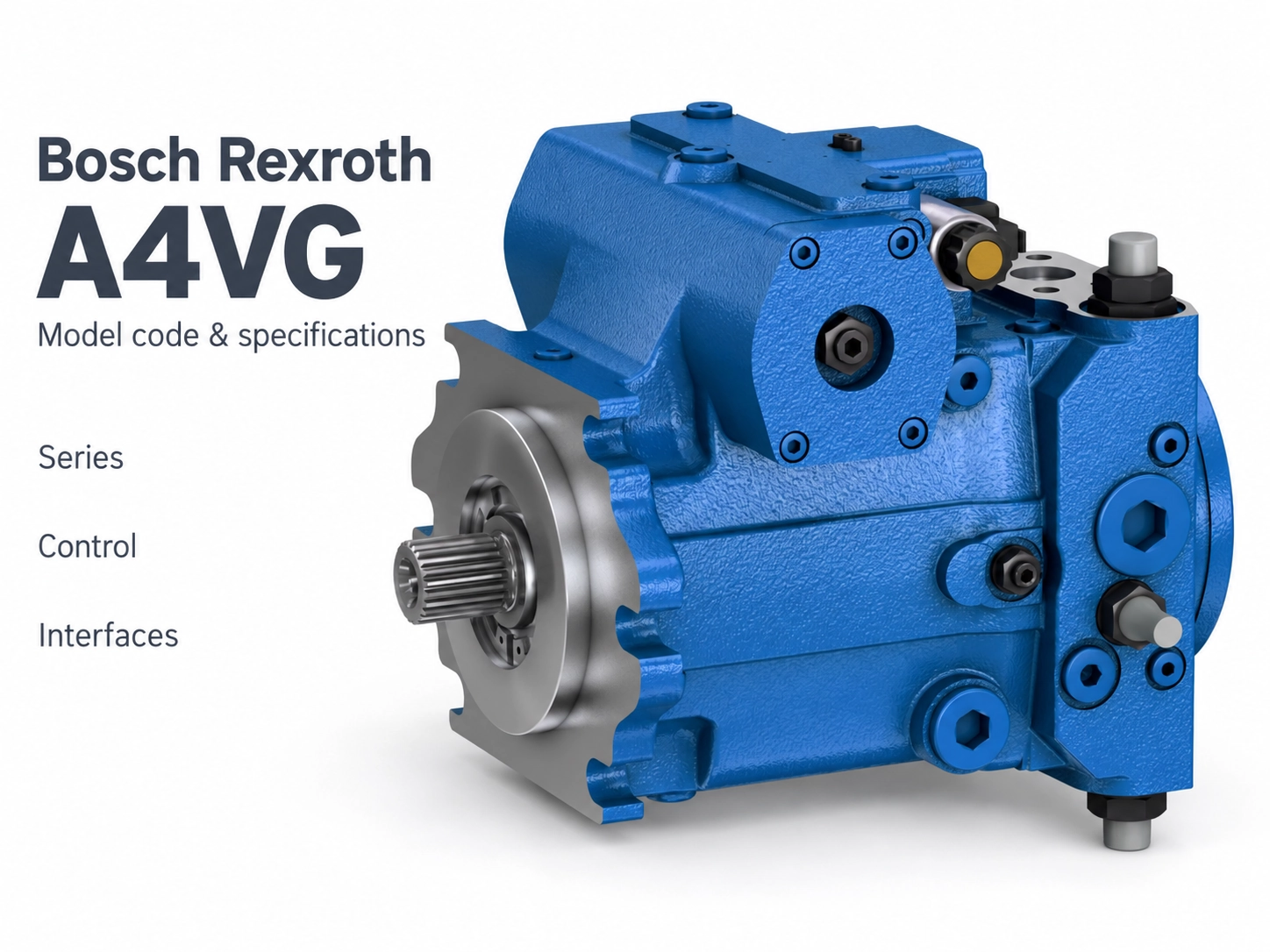
An A4VG model code describes a pump configuration. To read it, first identify the series and the applicable regional data sheet, then match each code field to that document. A short designation such as A4VG125 is insufficient to establish a complete replacement specification.
This guide compares named editions of Bosch Rexroth documentation. It explains Series 32 fields, selected AA4VG differences and changes in Series 40 field numbering. The original availability tables and the particular pump specification remain necessary for ordering.
What the code tells you
"Model code" is the term used here for the configuration string. The 2012 Series 32 document labels its table "Ordering code for standard program"; the 2018 AA4VG and 2020 Series 40 documents use "Type code." Start with the table in the document that matches the pump. (RE 92003/06.12, p. 2, RE-A 92003/06.2018, p. 2, RE 92004/2020-03-30, p. 2)
The useful question is whether every field in your recorded string has an explanation in the matching document. An unexplained suffix or a control option absent from that edition is a reason to check the document and the pump identity before proceeding.
First, identify the series and regional document
Series 32 and Series 40
In the editions below, the series field is numbered 10. Its values are 32 and 40. Check that field before interpreting the remaining configuration.
The pressure values below apply to ports A or B in the cited documents, with mineral-oil-based hydraulic fluids. They describe the documented Bosch Rexroth units, not the ratings of a separately supplied replacement.
| Document and scope | Nominal pressure | Maximum pressure | Maximum-pressure duration limits |
|---|---|---|---|
| RE 92003/06.12 - A4VG Series 32 | 400 bar absolute | 450 bar absolute | 10 s per operating period; 300 h total at the document's nominal speed, n_nom |
| RE 92004/2020-03-30 - A4VG Series 40 | 450 bar | 500 bar | 10 s per operating period; 300 h total; see the pressure diagram on p. 8 |
Pressure terminology follows each source: Series 32 explicitly labels these values as absolute pressure; the Series 40 A/B table prints them in bar without that qualifier. Nominal pressure is the document's maximum design pressure. Maximum pressure is time-limited, and the individual periods count toward the total. These values are not adjustment instructions or unconditional continuous-duty ratings. (Series 32, p. 7, Series 40, pp. 7–8)

Americas documentation and AA4VG
RE-A 92003/06.2018 covers AA4VG Series 32, Americas, with nominal sizes 28–125. Nominal size is abbreviated NG in the tables. Its code options differ from the 2012 A4VG Series 32 document:
| Field | A4VG - RE 92003/06.12 | AA4VG - RE-A 92003/06.2018 |
|---|---|---|
| 13: shaft options | Z, A, S, T, U | S, T, U |
| 14: flange options | C, D, F | C, F |
| 15: port-layout options | 02, 03, 10, 13 | 52, 53, 60, 63 |
These are option sets across the sizes covered by each document. They are not equivalent-code pairs, and not every option is available at every size. A code absent from one table may belong to a different regional program or edition; it does not automatically identify an incorrect nameplate. (A4VG, p. 3, AA4VG, pp. 2–3)
Reading an A4VG model code field by field: Series 32
The numbers below identify fields in RE 92003/06.12, not individual characters. A field can contain several characters, and some optional fields have no printed code. These tables explain the fields; they are not a list of all permitted combinations. Check the original size columns, control matrix and footnotes before accepting a configuration.
Fields 01–09: unit, control and control-related options
| Field | Code | Meaning and key condition |
|---|---|---|
| 01 | A4V | Variable-displacement swashplate unit. |
| 02 | G | Pump for a closed circuit. |
| 03 | Size designation | Nominal size (NG); match the size column on p. 2 and the displacement data on p. 8. |
| 04 | NV; HD3; HW; DG | NV: no control module. HD3: hydraulic proportional control responding to pilot pressure. HW: hydraulic proportional control with mechanical servo. DG: direct hydraulic control. |
| 04 | EP3; EP4; EZ1; EZ2; DA1; DA2 | EP: electric proportional control. EZ: electric two-point control. DA: speed-related automatic control. EP3, EZ1 and DA1 use 12 V DC; EP4, EZ2 and DA2 use 24 V DC in this edition. |
| 05 | D | Standard pressure cut-off. The code does not state its individual pressure setting. |
| 06 | L; otherwise no code | Neutral-position switch, for HW control only. |
| 07 | M; otherwise no code | Externally adjustable mechanical stroke limiter. |
| 08 | T; otherwise no code | X3/X4 ports for stroking-chamber pressure. |
| 09 | 1; 2; 3R; 3L; 4; 8; 7 | DA-valve selection: 1 means no DA valve; 2 means a fixed-setting DA valve. Other codes are an index here: consult p. 2, "DA control valve," for lever actuation, braking-inch-valve and pilot-device-port variants and their control restrictions. |
Read EP3 as one complete field. Expressions such as "EP3/4" are shorthand for two alternatives, not a token to copy into a model string. The field 09 matrix must be checked against the main control; the presence of a DA-valve field does not mean the main control is DA. (RE 92003/06.12, p. 2; pressure cut-off, p. 55)
Fields 10–17: series, seals and mechanical interfaces
| Field | Code | Meaning and key condition |
|---|---|---|
| 10 | 32 | Series 32. |
| 11 | R; L | Clockwise; counter-clockwise, viewed on the drive shaft. |
| 12 | N | NBR (nitrile rubber) seals with an FKM (fluoroelastomer) shaft seal. It does not mean every seal is NBR. |
| 13 | Z; A | DIN 5480 splined shafts: Z for a single pump; A for the first pump in specified combination-pump sizes. Check p. 3 and its standard-shaft footnote. |
| 13 | S; T; U | ANSI B92.1a splined shafts: S for a single pump; T for the first pump in specified combinations; U only for the second pump, at NG40 or NG90. Use the size columns and footnotes on p. 3. |
| 14 | C; D; F | SAE J744 mounting patterns: C is 2-hole at NG28–56; D is 4-hole at NG180 and NG250; F is 2+4-hole at NG71–125. |
| 15 | 02; 03; 10; 13 | Port-layout index: consult p. 3, "Service line ports," for the A/B flange-port arrangement, suction-port S position and size availability. These four values are not interchangeable. |
| 16–17 | N00; K..; F00; F.. | N00: no integrated boost pump and no through drive. K..: through drive without an integrated boost pump. F00: integrated boost pump without through drive. F..: integrated boost pump with through drive. |
| 17 | Through-drive interface selection | For K.. or F.., match the rear flange and coupling together in p. 3, "Through drives"; check the mounting-options overview on p. 52 and the combination-pump requirements on p. 53. The dots indicate an interface selection to resolve, not a complete specification. |
The shaft, mounting flange and rear-drive coupling are separate checks. A known flange code leaves the shaft and any attached pump interface to be confirmed. Preserve the source's pump-position restrictions when recording your result. (RE 92003/06.12, pp. 3 and 52–53)
Fields 18–22: valves, filtration, sensing and suffixes
| Field | Code | Meaning and key condition |
|---|---|---|
| 18 | 1; 3; 5; 4; 6 | Relief-valve index: consult p. 4, "Valves," for pilot/direct operation, bypass, differential-pressure setting range and size restrictions. A valve code alone does not give the fitted pressure setting. |
| 19 | S; D; K | S: boost-pump suction-line filtration. D: pressure-line filtration using external filter ports. K adds a cold-start valve to the external-filter-port arrangement. |
| 19 | F; P; B | Mounted filter with cold-start valve. P adds a visual contamination indicator; B adds an electrical indicator. Check size availability on p. 4. |
| 19 | E | External boost supply for versions without an integrated boost pump, N00 or K... |
| 20 | R; otherwise no code | Electric swivel-angle sensor; R here is not a rotation code. The source asks users to contact the manufacturer if the sensor is used for control. |
| 21 | P; Q | Two-pin DEUTSCH solenoid connector: P without a suppressor diode; Q with a diode, restricted to EZ and DA. |
| 22 | No code; -K; -S; -SK | Standard version: no code; standard with an attachment: -K. Special version: -S; special with an attachment: -SK. The suffix category does not explain the particular attachment or special execution. |
Do not transfer a letter's meaning between fields: F in the boost-pump selection and F in the filtration selection identify different features. For a special version, keep the suffix and obtain the specification that explains the deviation. (RE 92003/06.12, p. 4)
Worked field fragments
The following are teaching fragments, not a complete ordering code or a customer nameplate. Each row is independent; the rows do not establish an orderable combination.
| Fragment and known location | Reading under RE 92003/06.12 | What remains to confirm |
|---|---|---|
| EP3 in field 04 | Electric proportional control, 12 V DC | The remaining control-related options and actual electrical specification. |
| 32 in field 10; R in field 11; N in field 12 | Series 32; clockwise viewed on the drive shaft; NBR seals with an FKM shaft seal | Shaft, flange, ports and other configuration fields. |
| F00 across fields 16–17 | Integrated boost pump; no through drive | Other fields and suitability for the machine's required arrangement. |
| F in field 19 | Mounted filter with a cold-start valve | Size availability and the filter arrangement required by the installation. |
| -S in field 22 | Special version | The document describing that specific special execution. |
Sources: RE 92003/06.12, pp. 2–4. A useful decoding record keeps the original token, its field number, the document edition and any unresolved detail together. Where the document does not explain a field, record it as unresolved instead of substituting a familiar code.
Use this record structure for each field in the actual model string:
| Record item | What to enter |
|---|---|
| Original token | Copy the characters exactly. Record unreadable or missing characters as such; do not reconstruct them. |
| Source | Document number, edition, region and printed page number. |
| Field and meaning | Field number and the interpretation supported by that document. |
| Availability check | Size column, relevant control-column intersection, availability symbol and applicable footnotes. |
| Unresolved details | Missing identification, special-execution information or differences requiring supplier confirmation. |
For field 09, record the valve/control intersection; for field 15, the port arrangement and size availability; for field 17, the rear flange, coupling and attached-pump restrictions; and for field 18, the valve variant, size restrictions and separately confirmed pressure setting. An unexplained or unreadable character remains unresolved until supported by the pump's documentation.
How Series 40 numbering differs
Changing 32 to 40 does not convert a Series 32 specification into a Series 40 specification. The field order changes as well.
| Configuration item | Series 32 - 06.12 | Series 40 - 2020-03-30 |
|---|---|---|
| Unit / circuit / size / control / cut-off | 01–05 | 01–05 |
| Neutral switch | 06 | Within control selection |
| Stroke stop / X3–X4 options | 07 / 08 | 08 |
| DA valve | 09 | 09 |
| Series | 10 | 10 |
| Thread system | No separate field | 11 |
| Rotation | 11 | 12 |
| Seals | 12 | 13 |
| Flange | 14 | 14 |
| Shaft | 13 | 15 |
| Working-port layout | 15 | 16 |
| Boost arrangement / rotary-group selection | 16: boost arrangement | 17 |
| Through drive | 17 | 18 |
| Relief valves | 18 | 19 |
| Filtration / external supply | 19 | 20 |
| Angle sensor | 20 | 07 |
| Solenoid connector | 21 | 06 |
| Pressure sensor | No separate field | 21 |
| Other sensors | No separate field | 22 |
| Standard/special version | 22 | 23 |
This comparison is restricted to the named editions and maps field categories, not interchangeable code values. Series 40 field 08 also contains additional functions beyond the two listed here. Matching field numbers do not establish matching meanings or availability. (Series 32, pp. 2–4, Series 40, pp. 2–5)
Thread specification also needs its regional context. In RE 92004/06.12, Series 40 field 11 uses M for metric port threads with ISO 6149 O-ring sealing. That document still describes SAE flanged working ports separately. "Metric threads" and "SAE flange" identify different interface details and can appear in the same specification. Apply this reading to that edition; do not extend it to every regional Series 40 document. (RE 92004/06.12, p. 3)
Why the visible character count does not match the field count
An omitted option and a printed zero are different coding conventions. Do not insert zeros simply to make a Series 32 string look the same length as a Series 40 string.
For AA4VG in RE-A 92003/06.2018, field 06 has no code when the neutral switch is absent; L is restricted to HW control. Field 21 can also be omitted for purely hydraulic control. (AA4VG, pp. 2 and 4)
In Series 40 RE 92004/06.12, the absence of a solenoid connector is represented by 0 at field 06, while the absence of the angle sensor is 0 at field 07. The numbering and the printed string must both be read using that edition. (Series 40, p. 2)
One further distinction matters: the DA control-valve field is not exclusive to DA main control. In the Series 32 table, some DA-valve options are available with HD, HW, DG or EP controls. Check the intersection of the valve option and control column instead of skipping field 09 when the main control is not DA. (RE 92003/06.12, p. 2)
Use size to narrow the search, then confirm the series
The size lists change between documents. Keep them separate. Leading zeros below preserve the cited edition's notation; do not remove characters from a recorded model string to make it resemble another table.
| Document | Series / regional scope | Sizes listed |
|---|---|---|
| RE 92003/06.12 | A4VG Series 32 | 28, 40, 56, 71, 90, 125, 180, 250 |
| RE-A 92003/06.2018 | AA4VG Series 32, Americas | 28, 40, 56, 71, 90, 125 |
| RE 92004/06.12 | A4VG Series 40 | 045, 065, 085, 110, 145, 175, 210, 280 |
| RE 92004/2020-03-30 | A4VG Series 40 | 110, 125, 145, 175, 210, 280 |
Sources: p. 2 in the 2012 Series 32, 2018 AA4VG, 2012 Series 40 and 2020 Series 40 documents.
NG125 appears in both Series 32 RE 92003/06.12 and Series 40 RE 92004/2020-03-30. A4VG125 alone therefore does not determine the series. Likewise, the absence of a size from a later document's table does not, by itself, establish discontinuation or a replacement recommendation.
Use this lookup to choose which document to investigate. Confirm the series field before transferring any code interpretation into a quotation request. If the series is outside this guide's scope, obtain its matching documentation rather than forcing it into one of these tables.

Where to get the matching data sheet
Start at Bosch Rexroth Data sheets and Catalogs. The official search accepts a material number, product name or document/edition number. Signing in may provide additional documents.
Use the full manufacturer identification available for the pump. Check the document's product family, series, region, language and cover edition before using its code table. For the documents reviewed here, 92003 identifies the Series 32 reference and 92004 the Series 40 reference. Retain regional designations such as RE-A in RE-A 92003/06.2018; do not reduce the reference to its numeric part.
The PDF links in this article lead to Bosch Rexroth documents hosted by third parties. They allow the cited editions to be checked, but their availability does not establish that they are the current documents for your pump. The official search entry is a way to locate matching information, not confirmation that every option in these historical editions remains available.
For an existing pump, identify the document that explains its actual configuration. For a new order, obtain confirmation of the applicable current options. A newer publication date alone does not resolve a regional or configuration mismatch.
Decoded your code? Confirm the complete specification
Keep the following together when requesting a replacement review:
- The complete recorded model string, including punctuation and suffixes.
- A readable nameplate photograph and any available manufacturer identification details.
- The document number and edition used for decoding.
- Any fields that remain unresolved or differ from the proposed replacement.
- The installation drawing and operating requirements available for the machine.
Send this record to the supplier reviewing your request and ask for written confirmation of the proposed configuration against your recorded code and drawing, including unresolved fields and identified differences. The useful result is a documented configuration comparison. A successful field-by-field interpretation is a starting point for that confirmation, not proof of replacement compatibility.
Method and disclosure. This guide compares published Bosch Rexroth documentation; it contains no company test results or customer case claims. References to A4VG and AA4VG identify the documented pump families. The cited ratings describe those documents' scope and do not establish the ratings or compatibility of a separately supplied product. This article is a reference for identification and specification review, not installation, commissioning or pressure-adjustment instructions.