
If you are holding a pump with A11VO60DRS/10R-NSC12N00 or something similar stamped on the nameplate, you are not choosing a pump. You are verifying one. Every character in that string records a decision someone made when the unit was originally ordered, and every field has to be checked before a replacement is quoted. Some fields must be matched as ordered. Direction of rotation and the drive-shaft interface should not be treated as ordinary machine-side adjustment items. Other differences, such as port-thread configuration, should only be accepted after the interface and operating conditions have been checked and documented.
This guide translates an A11VO or A11VLO code field by field, so you can turn a nameplate photo into a written specification a supplier can quote against. It covers both generations currently in the field, which use different code structures and different size ranges, and it ends with a confirmation list you can paste straight into an email.
All technical values below come from the published Bosch Rexroth data sheets for these pumps: RE 92500 (Series 1x, version 2023-05-11) and RE 92510 (Series 40, version 05.2016). Document numbers and versions are given with each value, because the two documents do not agree on everything and an answer is only correct against a stated version.
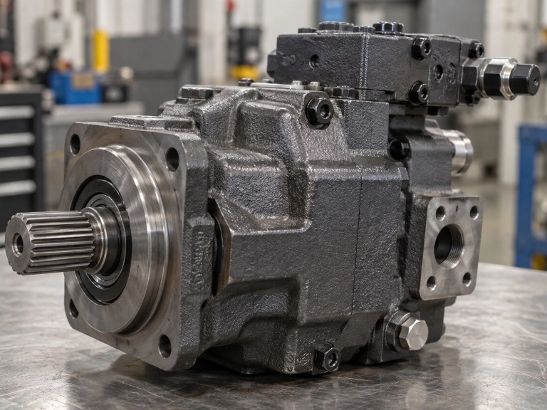
Find the code first - where it is on the pump
The type code is on the nameplate, normally on the housing near the mounting flange or on a flat face of the pump body. On an installed unit it may face a wall or be obscured by paint overspray or dried oil film.
For a quote-ready photo, capture the full string in one frame without cropping. Include the through-drive designation and any trailing option or version characters. The through-drive field determines whether a second pump can be mounted, while later positions can also change the ordered configuration.
Capture the material number, MNR or R-number as well if it is legible. For example, R902228077 is catalogued separately from the type code A11VO60DRS/10R-NSC12N00. More on that below.
If the nameplate is dirty rather than worn, clean it before photographing rather than reading through the film. A misread S for 5, or Z for 2, produces a code that looks plausible and is wrong.
Which generation do you have? Series 1x vs Series 40
Do this before decoding anything else, because Series 1x and Series 40 use different ordering structures and size lists; size 145 is the only nominal size shared by both lists.
Look at the digits immediately after the slash. /10 or /11 means Series 1x, described in RE 92500. /40 means Series 40, described in RE 92510 - there, the two digits are a single field meaning series 4, index 0, not a series-and-index pair the way Series 1x reads. These are not sequential revisions of one product. They are two separate data sheets with different code lengths, different size ranges and different pressure ratings.
| Difference | Series 1x (RE 92500/2023-05-11) | Series 40 (RE 92510/05.2016) |
|---|---|---|
| Sizes offered (A11VO) | 40, 60, 75, 95, 130, 145, 190, 260 | 110, 145, 175, 210, 280 |
| Sizes offered with charge pump (A11VLO) | 130, 145, 190, 260 | 145, 175, 210, 280 |
| Code positions | 15 | 21 |
| Nominal pressure | 350 bar | 350 bar (5100 psi) |
| Maximum pressure | 400 bar | 420 bar (6100 psi) |
Sources: Bosch Rexroth RE 92500, Series 1x data sheet and Bosch Rexroth RE 92510, Series 40 data sheet, both hosted by third parties.
The size lists are mostly, but not entirely, separate. Only size 145 appears in both. Sizes 110, 175, 210 and 280 exist only in Series 40; sizes 40, 60, 75, 95, 130, 190 and 260 exist only in Series 1x. This is why an A11VO210 code cannot be found in the Series 1x tables. Without checking the generation first, a valid Series 40 size can be mistaken for a typing error.
One more distinction applies to both generations. A11VO is the pump without an integrated charge pump; A11VLO is the version with one.
What each Series 1x code field decides
RE 92500/2023-05-11 numbers the Series 1x code as 15 positions. The table below is written to be worked through against your own nameplate: read the field, write down what you have, and check what would fail if a replacement differed there. The example column follows A11VO60DRS/10R-NSC12N00 throughout.
| # | Code field | Example | What it means | What fails if it doesn't match |
|---|---|---|---|---|
| 01 | Axial piston unit | A11V | Swashplate design, variable, 350 bar nominal / 400 bar maximum | Wrong product family entirely |
| 02 | Operating mode | O | O without charge pump; LO with charge pump (sizes 130–260) | Inlet conditions and permissible speed change; suction port size and rating differ |
| 03 | Size (NG) | 60 | Nominal displacement, 40 to 260 | Flow, torque and speed limits all move together |
| 04 | Control device | DRS | Pressure controller with load sensing | Control behaviour and control-port requirements may differ |
| 05 | Series | 1 | Series 1x, read against RE 92500 | Wrong data sheet, wrong tables |
| 06 | Index | 0 | Index 0 for sizes 40–130; index 1 for sizes 145–260 | Specifies a size/index pair that does not exist |
| 07 | Direction of rotation | R | Clockwise viewed on the drive shaft; L counter-clockwise | Ordered configuration; match R/L before replacement |
| 08 | Sealing material | N | NBR, with FKM shaft seal ring; V is FKM throughout | Temperature window changes at both ends |
| 09 | Drive shaft | S | Z DIN 5480 (single and combination); P parallel keyed DIN 6885; S ANSI B92.1a-1976 single pump; T ANSI B92.1a-1976 combination pump | Does not couple to the existing drive; also changes the permissible input torque |
| 10 | Mounting flange | C | C SAE J744 2-hole (sizes 40, 60); D SAE J744 4-hole (75–260); G SAE J617 / SAE 3 (95–190) | Bolt circle and pilot do not match the bell housing |
| 11 | Working port | 12 | 12 metric port thread to DIN 3852; 07 UNF port thread to ISO 11926 | Connection hardware differs; verify the port standard and installation drawing before accepting a substitution |
| 12 | Through drive | N00 | N00 none; otherwise a K designation identifying flange size and hub | Second pump cannot be driven |
| 13 | Swivel angle indicator | blank | Blank, V optical, R electric sensor | Changes the part number; R adds an electrical interface |
| 14 | Connector for solenoids | blank | P DEUTSCH molded 2-pin, on solenoid-operated controls | Mating connector on the machine no longer fits |
| 15 | Standard/special version | blank | Blank standard, S special, Y installation variant | A non-blank value means an installation drawing is required before assuming equivalence |
Three fields carry more consequence than a table row can hold.
Control device. This is the longest list in the code and the one with the widest functional consequence. RE 92500 documents power controllers (LR with its override, pressure cut-off, remote-control, load sensing and stroke-limiter variants such as LRC, LR3, LG1, LG2, LE2, LRD, LRDS, LRS2, LRS5, LRH1, LRH2, LRU2, LRU6), pressure controllers (DR, DRS, DRG, DRL), pilot-pressure related hydraulic controls (HD2, HD2D) and electrical controls with proportional solenoid (EP2, EP6, EP2D, EP2G2, EP2G4). Not every combination exists - the data sheet excludes several, and LRS5, EP2G2 and EP2G4 are not offered below size 95. Write the control block exactly as it appears rather than summarising it; a pump with the correct displacement and a different control letter group may physically fit while behaving differently from what the circuit requires.
Sealing material. N is not simply "NBR seals": RE 92500 specifies NBR with an FKM shaft seal ring. V is FKM. The two options have different operating windows. The hydraulic-fluid table in RE 92500/2023-05-11 also marks the NBR option as a special version and says to contact the manufacturer, so a historical N code should not be treated as proof of current standard availability.
Through drive. N00 means no through drive. Everything else is a specific K designation identifying a SAE J744 flange size together with a hub for a particular splined shaft - not a continuous numbering series. RE 92500/2023-05-11 groups them by flange: K01 and K52 on the 82-2 (A) flange; K02, K04 and K79 on 101-2 (B); K07, K24, K80 and K61 on 127-2 (C); K86, K17, K81, K82 and K83 on 152-4 (D); K72, K84 and K67 on 165-4 (E). Availability is size-dependent within each group, so a designation that exists in the table is not automatically available on your size. The same data sheet also lists, for each K designation, which second pumps can be mounted and on which shaft - for example K61 takes an A11VO size 60 on a Z shaft, or an A4VG/32 in sizes 40, 56 or 71. That table, not the K code alone, is what tells you whether the stack you have in mind is buildable.
Reading a Series 40 code
Series 40 codes have 21 positions (RE 92510/05.2016), and they are not the Series 1x code with extra characters. The structural differences that change how you read them:
The control function is spread across several positions instead of one. Where Series 1x carries a single control block such as LRDS, Series 40 separates a basic controller (LR, L3, L4, L5, L6, CR, PR, E1, E2, H3, H4, DR, DG, D2, M2) from additional pressure control (DR, DG), additional stroke control or unloading (E1, E2, H3, H4), load sensing (S0), and the depressurised basic position and external control pressure supply (A, B, C). The data sheet allows at most two additional controllers on top of the basic one. To compare a Series 40 unit against a Series 1x unit by control behaviour, you have to read several positions together.
Position 12 switches the whole thread system, not just the ports. M means every fastening thread to DIN 13 and every port thread with an O-ring seal to ISO 6149; A means fastening threads to ASME B1.1 and port threads to ISO 11926. This is a wider split than the Series 1x 12/07 choice, which changes the port thread while leaving the fastening threads metric, and it is not something an adapter fitting resolves.
Sealing is not a choice in the same way. RE 92510 lists only V (FKM) in the standard ordering table at position 14. The same data sheet notes that operation below −25 °C requires an NBR shaft seal, a special configuration identified by the letter K at that position, with a permissible range of −40 °C to +90 °C and referral to the manufacturer. If you are used to specifying NBR on Series 1x pumps, do not carry that habit across; check the order documentation for the actual unit rather than inferring from the standard row.
Flange and shaft designations use a different notation. Series 40 flanges are D4 (SAE J744 152-4, sizes 110 and 145), E4 (SAE J744 165-4, sizes 175 to 280) and G3 (SAE J617 409-12). Shafts are T1, T2, T3 to ANSI B92.1a and A1, A2, A4 to DIN 5480. A D in a Series 1x code and a D4 in a Series 40 code are entries in different tables and should not be treated as equivalents.
Through-drive designations are two-part. Series 40 combines a flange attachment code with a hub code - A3S2, B3S4, C3S7, D4T1, E4T2 and so on, plus U000 for a unit prepared for through drive with a pressure-proof plugged cover. As with Series 1x, availability varies by size.
Positions exist that Series 1x does not have, including a swivel angle sensor option, a rotary group version (E noise-optimised for n = 1500/1800 rpm without charge pump, S with charge pump), and a pressure sensor position.
The practical rule: once you have identified /40, read the whole code against RE 92510 and stop consulting the Series 1x tables.
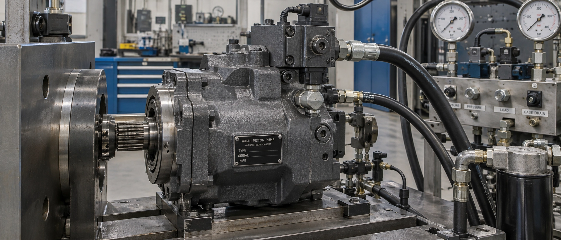
Worked example: decoding one real code end to end
Take A11VO60DRS/10R-NSC12N00, which appears in distributor catalogue records alongside material number R902228077. Read against RE 92500/2023-05-11, position by position:
A11V axial piston variable pump · O open circuit, no charge pump · 60 size 60 · DRS pressure controller with load sensing · /1 Series 1x · 0 index 0 · R clockwise viewed on the drive shaft · N NBR with FKM shaft seal ring · S splined shaft ANSI B92.1a-1976, single pump · C SAE J744 2-hole mounting flange · 12 metric port thread to DIN 3852 · N00 no through drive.
Two internal consistency checks are worth running on your own code as well. Index 0 is consistent with size 60, because index 0 applies to sizes 40 through 130 in this series; a code reading A11VO60… with index 1 would not be. Flange C is consistent for the same reason - SAE J744 2-hole is only offered on sizes 40 and 60, so a C on a size 130 code is a signal to go back to the nameplate photo before quoting.
Codes containing a plus sign. A long code with a + in the middle is not a typing error or two part numbers run together. RE 92500/2023-05-11 states on page 66 that when ordering combination pumps, the type designations for the first and second pump are joined by a +, and gives the order example A11VO130LRDS/10R-NZD12K61 + A11VO60LRDS/10R-NZC12N00. Split the string at the +, decode each half with the same tables, then check that the through-drive designation on the first pump matches the mounting and shaft of the second, and that the torque limits below are satisfied.
Five things people get wrong on an A11VO code
The index digit is not a version number. /10 is not an older pump than /11. In RE 92500/2023-05-11, index 0 applies to sizes 40 to 130 and index 1 applies to sizes 145 to 260. The index follows the size. Writing /10 on an enquiry for a size 145 unit specifies a combination that does not exist. Self-check: if your size is 145 or above, the index should read 1.
Rotation is an ordered configuration, not a normal field setting. The R or L position is specified in the type code, viewed on the drive-shaft end. Match it before ordering and do not assume an opposite-rotation unit is interchangeable through an ordinary machine-side adjustment. If an internal reconfiguration is being considered, it should be confirmed for the specific unit by a qualified repair or manufacturing source.
FKM is not automatically the better seal. RE 92500/2023-05-11 gives the NBR version a continuous fluid temperature limit of +85 °C measured at port T, with cold start permitted down to −40 °C at a viscosity up to 1600 mm²/s. FKM tolerates a higher continuous temperature, up to +110 °C, but its cold start limit is only −25 °C. The cold start values themselves carry conditions: up to 3 minutes, unloaded below 50 bar, at no more than 1000 rpm, with no more than 25 K difference between the unit and the fluid in the system. On a machine that sits outdoors in a cold climate, specifying FKM because it sounds like the premium option narrows the cold-start window by 15 °C. Choose on the actual temperature range at both ends, not on material reputation. For a new Series 1x order, also confirm current NBR availability because RE 92500/2023-05-11 flags the NBR option as a special version in its hydraulic-fluid table.
Going up a size does not give you a proportional flow increase. RE 92500/2023-05-11 lists n nom at Vg max and a separate n max row. The n nom values for A11VO apply at 1 bar absolute at suction port S with mineral-oil-based fluid. The n max values apply at Vg ≤ Vg max or when inlet pressure at port S is increased, and the permissible operating point must be checked against the data sheet's speed-limit curve. Do not multiply n max by full displacement as though it were the full-displacement rating. For the full-displacement reference, the data sheet gives 126 l/min at size 40, 158 at 60, 189 at 75, 220 at 95, 273 at 130, 319 at 145, 405 at 190 and 468 at 260, each at n nom and Vg max. The version with charge pump also changes the result: at size 130 the A11VLO is rated 2500 rpm and 325 l/min, while the A11VO is 2100 rpm and 273 l/min. Usable speed still depends on the actual inlet conditions and the confirmed configuration.
A through drive does not mean any second pump will fit. Two conditions have to hold at once. The hub identified by the K designation has to match the second pump's shaft, which is what the mounting-options table in RE 92500 resolves. And the torques have to stay inside two separate limits: the input torque, ME, is the sum of all pumps in the stack and must stay below ME max; the through-drive torque, MD, is the sum of the second and any third pump and must stay below MD max. Both are size-dependent, and ME max also depends on the drive shaft. The limiting shaft option varies by size, and for some combinations the shaft input-torque limit is more restrictive than the general through-drive limit. Look up ME max for your actual size and shaft, and MD max for your size, in RE 92500 or on the order confirmation rather than applying one number to every build.
When the nameplate is unreadable
If the type code cannot be read because of wear, paint or relabelling, use a second identification route.
The material number. A material number, MNR or R-number is separate from the type code. One verified catalogue example pairs R902228077 with A11VO60DRS/10R-NSC12N00 and lists the configuration field by field: Series 10 for sizes 40 to 130, clockwise rotation, NBR with FKM shaft seal, SAE J744 2-hole flange, ANSI B92.1a splined shaft and no through drive. That page is a third-party distributor listing rather than a manufacturer document, so treat it as a cross-check. If an MNR or R-number remains legible, use it with a manufacturer or distributor lookup to recover or verify the corresponding configuration rather than trying to decode the number itself.
The installation drawing. If the machine documentation survives, use it to verify the physical interfaces shown for the installed unit, such as flange, shaft and port arrangement.
The original order confirmation. This records the configuration supplied for that order and can resolve options that a current catalogue may not show in the same way.
Physical measurement as a last resort. Flange bolt pattern, shaft spline count and port thread can be measured and matched against the standards referenced in the code. This identifies the interface, but it does not recover the control device or the internal settings, so it narrows the field rather than closing it.
What to confirm before you order a replacement
Once the code is decoded, the output should be a list a supplier can quote against without a second round of questions. A useful intermediate step is to write the code back out as separated fields, so you can see what you actually have:
A11VO · size 60 · control DRS · series 1 · index 0 · rotation R · seal N · shaft S · flange C · port 12 · through drive N00
The following is written to be copied into an email.
- Full type code as read from the nameplate, including everything after the slash, plus a photo of the plate
- Material number / MNR / R-number (for example R902228077), if legible
- Series: 1x or 40, and the data sheet you are working from
- Size and, for Series 1x, the index digit consistent with that size
- Control device, written exactly as it appears, not summarised
- Direction of rotation, viewed on the drive shaft end
- Drive shaft type and the standard it follows, with spline count if known, and whether it drives a second pump
- Mounting flange designation
- Service line port designation, and for Series 40 the M or A thread system, with a note on whether interface changes are acceptable
- Through drive: N00, or the K designation (Series 1x) or flange-plus-hub designation (Series 40), together with the make, model and shaft of the second pump it drives, and the torque figures for the stack
- Sealing material, together with the actual minimum and maximum fluid temperatures at your site
- Fluid type in use, including whether it is a mineral oil, a fire-resistant fluid or a biodegradable fluid
- Filtration and cleanliness: RE 92500/2023-05-11 requires at least 20/18/15 to ISO 4406 for Series 1x, tightening to 19/17/14 where viscosity falls below 10 mm²/s at the drain port. RE 92510/05.2016 also requires at least 20/18/15 for Series 40, but tightens to 19/17/14 on a different trigger - fluid temperatures between 90 °C and 115 °C. Both sheets give an optimum viscosity range of 36 to 16 mm²/s and a continuous range of 400 to 10 mm²/s. These are stated operating conditions, not recommendations, and they are worth agreeing before the order rather than after a failure
- Installation drawing requested and checked against the machine before the pump ships
If you want the decoded specification cross-checked against what is actually available, see our A11VO replacement page and send the configuration for confirmation.
If your decoded code turns out to belong to a different family altogether, which can happen when the installed pump is not the configuration expected from the machine documentation, the axial piston pump range covers other pump families.
Frequently asked questions
What is the difference between A11VO and A11VLO?
LO denotes the version with an integrated charge pump (impeller); O is the version without. The charge pump fills the unit, which allows higher rotational speeds and easier cold starting, and in most cases removes the need to raise the inlet pressure externally. In Series 1x it is offered in sizes 130 to 260 (RE 92500/2023-05-11); in Series 40, sizes 145 to 280 (RE 92510/05.2016).
Does /10 mean an older pump than /11?
No. The index digit follows the size, not the production date. In RE 92500/2023-05-11, index 0 applies to sizes 40 to 130 and index 1 applies to sizes 145 to 260.
My code contains /40 and I cannot find my size in the Series 1x A11VO tables. Why?
Because /40 identifies Series 40, documented in RE 92510/05.2016 with sizes 110, 145, 175, 210 and 280. Sizes 110, 175, 210 and 280 do not appear in the Series 1x data sheet at all.
Can I treat an opposite-rotation A11VO as interchangeable?
No. The R or L position is an ordered configuration, defined as viewed on the drive-shaft end (RE 92500/2023-05-11). Match the rotation at the point of order and do not assume the opposite code can be corrected by an ordinary machine-side adjustment. Any internal reconfiguration should be confirmed for the specific unit by a qualified repair or manufacturing source.
What oil cleanliness does an A11VO require?
Both generations require at least 20/18/15 to ISO 4406. The trigger for tightening to 19/17/14 differs: viscosity below 10 mm²/s at the drain port for Series 1x (RE 92500/2023-05-11), fluid temperature between 90 °C and 115 °C for Series 40 (RE 92510/05.2016).
Send us the code
If you have the nameplate photo and a filled-in version of the confirmation list above, send both to our team for configuration review. We can then confirm which fields can be matched directly, which interfaces need a drawing check, and which configurations we do not supply. Enquiries go through the A11VO replacement page.
Sources and scope. Technical values in this article are taken from the published Bosch Rexroth data sheets RE 92500 (version 2023-05-11) and RE 92510 (version 05.2016), accessed through the third-party hosted copies linked above. The material number example is cross-checked against a third-party distributor catalogue record, not a manufacturer document. ISO 3019-1:2001 and SAE J744-2021 are referenced by standard number and scope only; the paid dimensional tables are not reproduced here. Where an older unit carries a control designation not listed in the current data sheet, check the corresponding earlier version, RA 92500-A/06.09, rather than assuming the designation is invalid.
Disclosure. A11VO and A11VLO are Bosch Rexroth product designations. Sheungchak supplies non-OEM replacement pumps and is not affiliated with Bosch Rexroth.