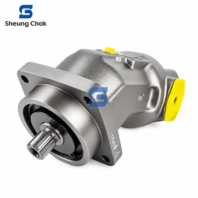

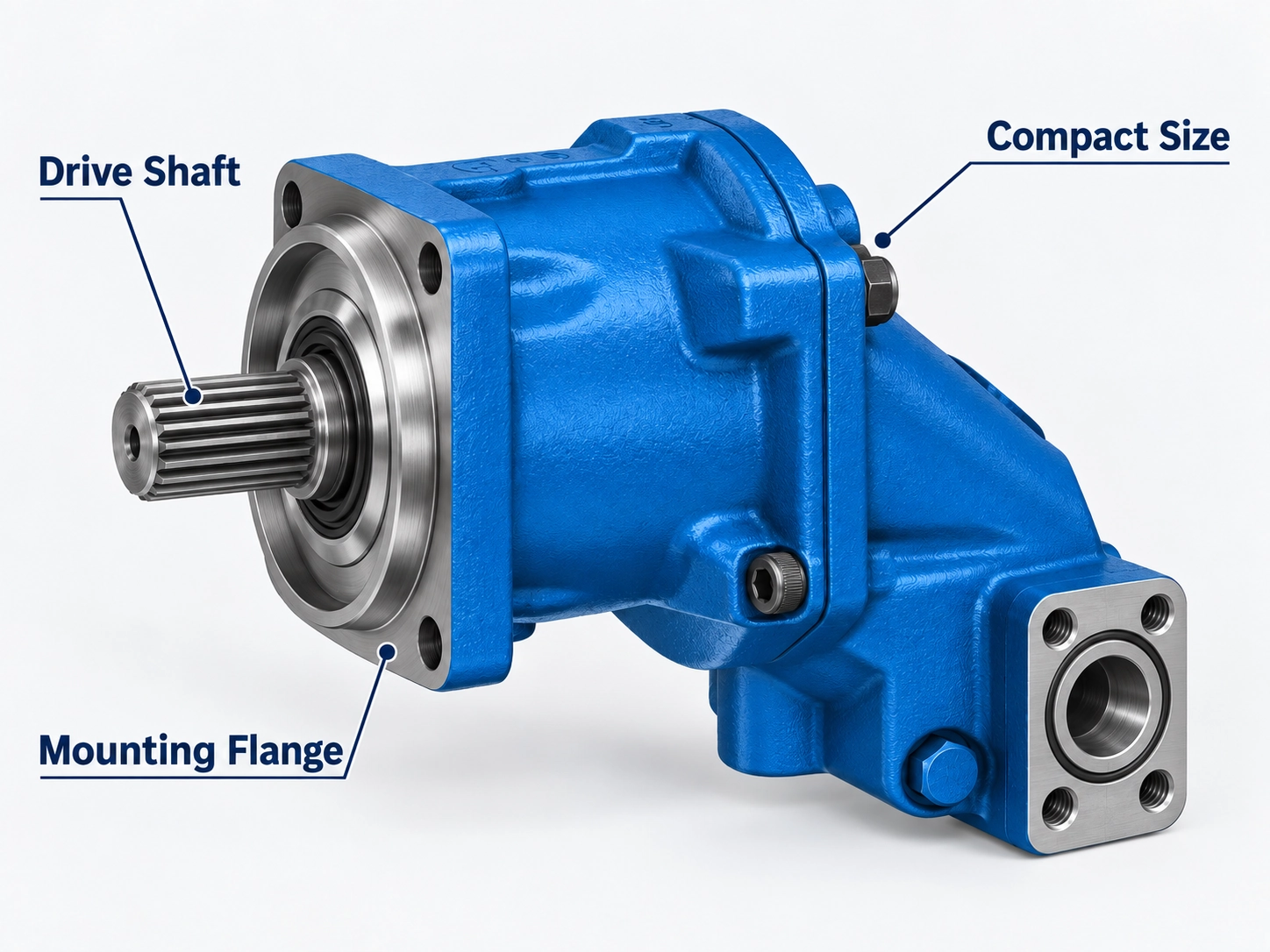
An A2FM model code identifies one specific configuration of a Bosch Rexroth bent-axis fixed displacement motor. It records the size, series, drive shaft, mounting flange, working ports, rotation convention, seals, and any integrated valves or speed sensor. Read correctly, it tells you what will physically fit and what pressure that exact configuration is rated for. Read against the wrong data sheet, it tells you something confidently wrong.
That is the main risk with this family. Sizes 45 to 90 exist in two different code systems, series 6x and series 70, and the two systems do not share shaft, flange, port or valve characters. So this guide starts by identifying which system you are holding. It then works through the positions in order, using two real codes as worked examples.
Decoding a model code confirms what a unit is. It does not confirm that a replacement suits your machine. Shaft loading, case drain routing and the installation drawing still have to be checked, and the last two sections cover that.
Identify the series before you decode anything
A2FM motors are documented in two data sheets with different code structures.
Series 6x is documented in RE 91001. The size comes first, followed by the series digit and index after a slash, for example A2FM 32/61W-VBB020. In the 09.07 edition the index is 1 for sizes 10–180, 3 for size 200 and 0 for sizes 250–1000 (RE 91001/09.07, p. 2). Sizes 250–1000 can carry an L for the long-life bearing between A2F and M. Size 5 has its own short code, A2F 5/60W-…, without the M.
Series 70 is documented in RE 91071. A pressure-range letter (N, M or H) follows A2FM directly, before the size, and the series appears as /70. A typical code is A2FMM90/70NWVN4Z907W000 (RE 91071/06.2018, pp. 2–3, 22).
Two quick tests separate them:
- N, M or H immediately after A2FM (A2FMN, A2FMM, A2FMH) means series 70. Series 6x codes carry no pressure letter.
- /6… after the size (/61, /63, /60) means series 6x. /70 means series 70.
Size alone won't tell you. The 09.07 edition of RE 91001 lists sizes 45, 56, 63, 80 and 90 in series 6. The metric series 70 data sheet covers sizes 45 to 107, and the North American series 70 edition covers sizes 23 to 125. An older nameplate and a current catalogue can both be correct and still disagree. That is why the edition you decode against should match the vintage of the unit, not simply be the newest PDF available.
Metric or SAE?
In series 70 the metric/SAE difference is written into the code itself:
| Code position | Metric edition (RE 91071) | North American edition (RE-A 91071) |
|---|---|---|
| 06 – ports and fastening threads | N: ports to DIN 3852, fastening threads to DIN 13 | C: ports based on ISO 11926 (O-ring, UN threads), metric DIN 13 fastening threads; A: ISO 11926 ports with ASME B1.1 fastening threads |
| 09 – mounting flange | M4, N4 (ISO 3019-2, 4-hole) | B2, C4, D4 (SAE J744) |
| 10 – drive shaft | Z6/Z8/Z9 (DIN 5480 splines), P6/P8/P9 (DIN 6885 keys) | S7, V8, V9, T1 (SAE J744 splines to ANSI B92.1a), plus keyed P5–P9, B1 |
Sources: RE 91071/06.2018, p. 2; RE-A 91071/2021-01-15, pp. 2–3.
The North American edition also gives every pressure in psi alongside bar. In older series 6x literature the SAE version was sold under an AA2FM designation (RA 91 001/08.97). A doubled AA prefix is therefore a reliable SAE signal on older units. Its absence does not prove a unit is metric, so confirm the flange and port standard.
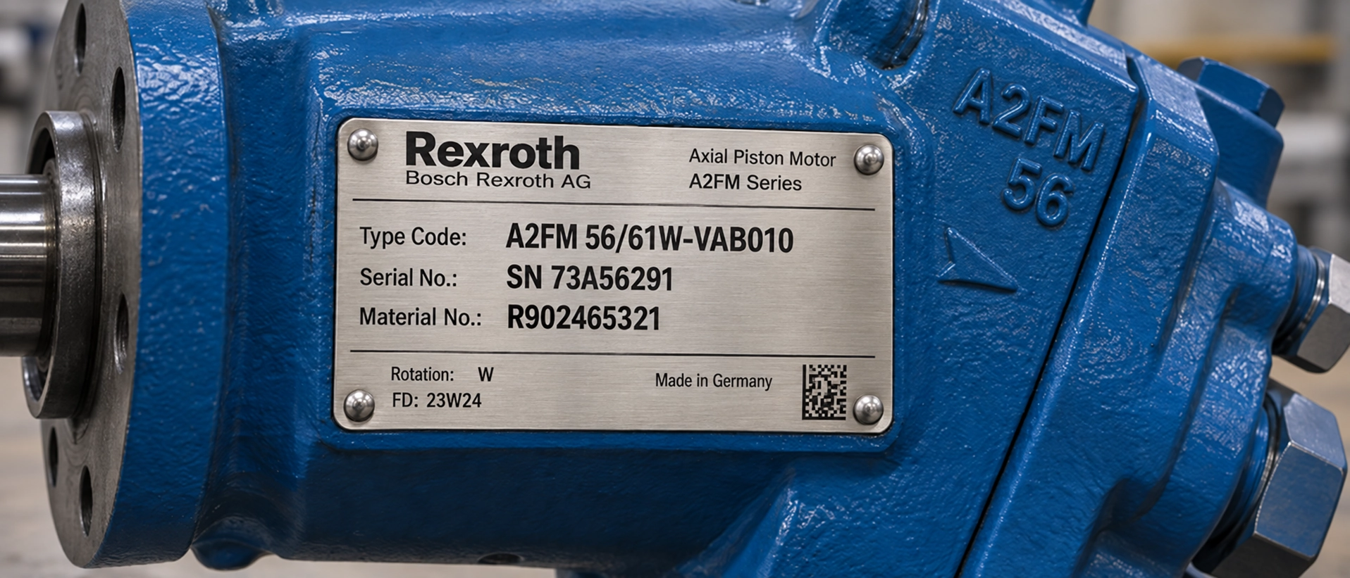
Record the complete nameplate
Decode from the nameplate, not from a partial code someone typed into an email. Capture at least these four fields:
- the full type code, including everything after the size;
- the material number (on Rexroth units, typically an R9-prefixed number);
- the serial number;
- the manufacturing date, if shown.
Photograph the plate straight on, in good light, rather than transcribing it. The characters most often lost in transcription are the trailing port, valve and sensor positions. Those are exactly the ones that decide whether the unit bolts up and connects.
Worked example 1: a series 6x code
Take A2FM 32/61W-VBB020, decoded against RE 91001/09.07:
| Segment | Meaning | Data sheet reference |
|---|---|---|
| A2F | Axial piston unit, bent-axis, fixed displacement | p. 2 |
| M | Motor (plug-in version is A2FE, separate data sheet) | p. 2 |
| 32 | Size: approx. 32 cm³/rev | p. 2 |
| 6 / 1 | Series 6, index 1 (sizes 10–180) | p. 2 |
| W | Rotation: alternating (bidirectional), viewed on shaft end | p. 2 |
| V | Seals: FKM | p. 2 |
| B | Shaft: parallel keyed, DIN 6885; for size 32 this is AS8x7x40 | pp. 2, 10 |
| B | Flange: 4-hole, ISO 3019-2 | p. 2 |
| 02 | Port plate: SAE flange ports A and B at side, opposite; SAE J518 1/2 in, M8x1.25 fastening threads | pp. 3, 11 |
| 0 | Valve: none | p. 3 |
| (none) | No speed measurement, standard version (no code characters) | p. 3 |
What this configuration is rated for: nominal 350 bar, peak 400 bar. That is not the 400/450 bar often quoted for "A2FM sizes 10–200", because shaft B carries the lower rating (RE 91001/09.07, pp. 5, 10). If this motor drives a pinion or a V-belt, it stays at 350/400 bar. The additional radial-load derating to 315/350 bar applies to shafts Z and P, not B.
Newer editions of RE 91001 exist, such as the 2019-09-17 edition. Availability of individual characters can change between editions, so if a unit postdates 2007, confirm each position in the edition that matches it.
Worked example 2: a series 70 code
A2FMM90/70NWVN4Z907W000 is the ordering example printed in RE 91071/06.2018 for a wheeled-excavator travel drive:
| Pos. | Segment | Meaning |
|---|---|---|
| 01–02 | A2F M | Bent-axis fixed unit, motor (standard version) |
| 03 | M | Pressure range M: nominal 400 bar, maximum 450 bar |
| 04 | 90 | Size 90 (90.5 cm³/rev) |
| 05 | 70 | Series 7, index 0 |
| 06 | N | Ports to DIN 3852, fastening threads to DIN 13 (metric) |
| 07 | W | Bidirectional, viewed on drive shaft |
| 08 | V | FKM seals |
| 09 | N4 | ISO 3019-2 flange 140-4 |
| 10 | Z9 | Splined shaft DIN 5480 W40x2x18x9g |
| 11 | 07 | Working port version with pressure relief valve, for mounting a BVD counterbalance valve |
| 12 | W | BVD counterbalance valve mounted |
| 13 | 0 | No speed sensor |
| 14 | 0 | Standard version |
| 15 | 0 | Standard version |
Source: RE 91071/06.2018, pp. 2–3, 7, 22.
What this configuration is rated for: the M range alone gives 400/450 bar. With the counterbalance valve fitted (07W), however, the data sheet limits operation to 350/420 bar and 220 l/min. The same restricted values apply to the pressure-relief-valve versions 09R and 09S. The counterbalance valve itself is ordered separately under its own type code. Here the valve positions at the end of the code change the pressure answer.
Size: what the displacement number does and doesn't tell you
The size number is the approximate geometric displacement in cm³ per revolution. The exact value is in the technical data table: size 90 in series 70 is 90.5 cm³, and size 107 in series 6 is 106.7 cm³.
That is all the number means. It does not fix the pressure rating, shaft, flange or port thread, and it does not identify the series. Two motors can share a size and share nothing else. Matching displacement is the start of a replacement check, not the end of one.
Drive shaft codes
The shaft position is where a mismatched replacement usually fails, because a wrong shaft is only discovered at installation.
In series 6x, the letter identifies the shaft type, and the dimensions depend on the size group. The same letter means a different shaft in the next group (RE 91001/09.07, pp. 9–10):
| Shaft | Type | Sizes 10, 12, 16 | Sizes 23, 28, 32 |
|---|---|---|---|
| A | Splined, DIN 5480 | W25x1,25x30x18x9g | W30x2x30x14x9g |
| Z | Splined, DIN 5480 | W20x1,25x30x14x9g (10, 12 only) | W25x1,25x30x18x9g (23, 28 only) |
| B | Parallel keyed, DIN 6885 | AS8x7x32 | AS8x7x40 |
| P | Parallel keyed, DIN 6885 | A6x6x32 (10, 12 only) | AS8x7x40 (23, 28 only) |
Larger sizes follow the same pattern with larger dimensions. Size 45 is offered only with Z and P, and sizes 250–1000 only with Z and P. Size 5 uses B (keyed) or C (tapered shaft to DIN 6888). Always read dimensions from the page for your size, not from the letter.
In series 70 the shaft code has two characters, and the digit indicates the diameter group: Z6/P6 are 30 mm, Z8/P8 35 mm and Z9/P9 40 mm in the metric edition. The North American edition uses SAE J744 splines: S7 is 1 1/4 in 14T 12/24 DP, V8 1 3/8 in 21T 16/32 DP, V9 1 1/2 in 23T 16/32 DP and T1 1 3/4 in 13T 8/16 DP (RE-A 91071/2021-01-15, p. 2).
A shaft character from a series 6x code has no defined meaning in a series 70 code. The shaft choice also affects permissible pressure, which the pressure section below covers.
Mounting flange and working port codes
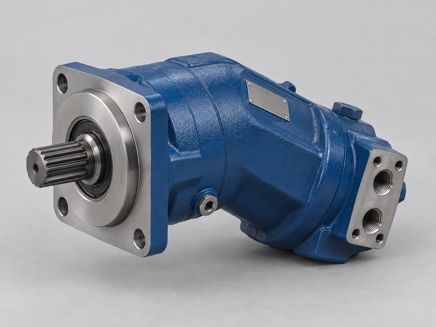
Flange. Series 6x uses B for a 4-hole ISO 3019-2 flange (sizes 10–250) and H for 8-hole (sizes 355–1000). Metric series 70 uses M4 (125-4) and N4 (140-4) on the A2FM. The plug-in A2FE uses P2/Y2, which is a different body and not interchangeable with an A2FM. North American series 70 uses SAE J744 B2, C4 and D4.
Working ports. This position combines location and connection form, and the two series structure it differently.
In series 6x, position 12 has three characters: a two-digit port plate code followed by a one-digit valve code (RE 91001/09.07, p. 3):
| Port plate | Description |
|---|---|
| 01 | SAE flange ports A and B, rear |
| 02 | SAE flange ports A and B, at side, opposite |
| 03 | Threaded ports A and B, at side, opposite |
| 04 | Threaded ports A and B, at side and rear |
| 10 | SAE flange ports A and B, bottom |
| 18 | Port plate for mounting a counterbalance valve |
| 19 | Port plate with pressure relief valves |
| Valve digit | Description |
|---|---|
| 0 | Without valve |
| 1 | Pressure relief valves, without pressure sequence range |
| 2 | Pressure relief valves, with pressure sequence range |
| 7 | Flush and boost pressure valve |
So 020 is side SAE ports without a valve, 027 the same plate with a flush and boost valve, and 191 a relief-valve plate. Threaded ports are metric to DIN 3852, and SAE flange ports are to SAE J518. Not every combination exists for every size.
In series 70, the working port (position 11) and valves (position 12) are separate positions. Ports are 11 (SAE, bottom), 02 (SAE, side), 05 (threaded, side), 07 (relief valve for BVD mounting) and 09 (relief valves); the North American edition adds 01 and 03. The valve position uses letters, covered in the next section.
If a character on your nameplate does not appear in the data sheet you are reading, do not substitute the nearest match. Work through this order instead:
- Confirm the series from the code structure, then open the matching data sheet: RE 91001 for 6x, RE 91071 or RE-A 91071 for 70.
- If the code is still missing, you are probably reading a different edition from the unit. Find one contemporary with its manufacturing date.
- If it is still missing, confirm the ports physically. Check the thread form and size, the port spacing, and whether the ports are SAE J518 split-flange or threaded DIN 3852 or ISO 11926.
- Record what you measured alongside the code when you request a quotation.
Rotation: why A2FM codes show "W"
Engineers used to pump codes often look for an R or L rotation character and cannot find one. That is expected. Both series use W, which RE 91001 describes as alternating and RE 91071 as bidirectional, viewed on the drive shaft.
A bent-axis fixed motor of this type is not handed. The output direction is set by which port is pressurised. In both data sheets, flow from A to B gives clockwise rotation viewed on the shaft, and flow from B to A gives counter-clockwise. There is nothing to specify at order time and nothing to match on a replacement.
Pump codes behave differently. Our A4VSO model code guide walks through the pump-side rotation characters if you are checking both units in one circuit.
Two practical notes. First, the recommended position of a driving gear relative to the shaft depends on the operating direction, because it affects bearing life. Both data sheets show this, so a unidirectional gear drive is still worth checking against the drawing. Second, one North American series 70 option, the check-valve port plate U, is only for one defined rotation direction.
Valves, sensors and special-version suffixes
These positions are easy to drop when a code is retyped, and dropping them is not harmless. An integrated valve changes the external envelope and adds connections. A speed sensor adds an electrical interface. Some valve versions also reduce the permissible pressure and flow.
Series 6x (RE 91001/09.07, pp. 3, 28–32):
- Valves: the last digit of the port position (0, 1, 2, 7), as tabled above. The flush and boost valve opens at a fixed 16 bar, and the relief valves can be set from 50 to 420 bar.
- Speed measurement:
D means prepared for an inductive ID sensor (sizes 23–180).
F means prepared for an HDD Hall-effect sensor (sizes 23–250).
"Prepared" means the sensor itself is not included.
No character means no speed measurement. -
Special version: J is the version for slew drive applications, standard with port plate 19.
Series 70 (RE 91071/06.2018, p. 3):
- Position 12, valves:
0: none.
C, E, F, G, I, J: integrated flushing and boost-pressure valve; the letter sets the orifice and flushing flow, from 2.6 to 12.5 l/min.
R / S: pressure relief valves without or with pressure sequencing stage.
W: BVD counterbalance valve mounted.
The North American edition adds further flushing orifices and U, a check valve.
- Position 13, speed sensor:
0: none.
A: prepared for DSA.
B: DSA mounted.
N / M: prepared for / mounted DSM (metric A2FM only).
- Position 14, special version:
0: standard.
L: long-life bearing. It is not offered with pressure range H, because H already includes it.
J: slew drives.
- Position 15, standard/special version:
0: standard.
Y: standard with installation variants, such as T ports opened or closed differently.
S: special version.
A unit that matches on size, shaft and flange but differs in these positions may not fit the same space, connect to the same harness or carry the same rating.
Pressure depends on the full configuration
Pressure is the value most often quoted loosely: a single figure attached to the name "A2FM". The data sheets do not support that.
Series 70 puts the pressure range in the code:
| Range | Nominal pressure | Maximum pressure | Metric edition sizes | North American edition sizes |
|---|---|---|---|---|
| N | 300 bar (4350 psi) | 350 bar (5100 psi) | 56–107 | 28–107 |
| M | 400 bar (5800 psi) | 450 bar (6500 psi) | 45–90 | 23–125 |
| H | 450 bar (6500 psi) | 500 bar (7250 psi) | 45–90 | 45–125 |
Sources: RE 91071/06.2018, pp. 1–2, 5; RE-A 91071/2021-01-15, pp. 1–2, 5.
A replacement that changes that letter changes the rating. As worked example 2 shows, relief-valve and counterbalance-valve versions are further limited to 350/420 bar. Shaft and radial load also matter here. In the North American edition, an A2FMM size 90 with the S7 spline is limited to 260 bar differential pressure at its maximum radial force, against 400 bar for the V8 and P9 shafts.
Series 6x has no pressure letter. The rating comes from the size group and the shaft (RE 91001/09.07, p. 5):
| Sizes | Shaft | Nominal / peak pressure |
|---|---|---|
| 5 | B (keyed) | 210 / 250 bar |
| 5 | C (tapered) | 315 / 350 bar |
| 10–200 | A, Z (splined) | 400 / 450 bar |
| 10–200 | B, P (keyed) | 350 / 400 bar |
| 250–1000 | Z, P | 350 / 400 bar |
Three conditions narrow this further:
- Radial loading, sizes 10–200: with shafts Z and P, drives with radial loading of the drive shaft, such as pinions or V-belts, are limited to 315 bar nominal and 350 bar peak.
- Size 56 with shaft Z is rated 350 / 400 bar.
- Pulsating load above 315 bar: the data sheet recommends splined shaft A (sizes 10–200) or splined shaft Z (sizes 45 and 250–1000).
In practice, pressure follows the size group, then the shaft code, then how the shaft is loaded. A unit whose size row says 400/450 bar is not automatically a 400/450 bar unit.
Limits the code does not show. Series 70 also requires the following (RE 91071/06.2018, p. 5):
- a minimum of 25 bar absolute on the high-pressure side;
- a maximum of 700 bar for the sum of pressures at A and B;
- a maximum averaged differential case pressure of 2 bar at the shaft seal, with peaks to 10 bar for under 0.1 s.
For series 6x, the 09.07 edition recommends not exceeding an average continuous case drain pressure of 3 bar absolute. Up to 6 bar absolute is permitted at reduced speed, with the same 10 bar short peaks. These are the limits a correctly decoded but incorrectly installed motor will violate.
Check the combination before you order
A decoded code tells you what a unit is. These checks tell you whether it will work where you are putting it.
- Series first, then every other position. Confirm 6x or 70, and metric or SAE, before reading any shaft, flange or port character.
- Match the data sheet edition to the unit's vintage, not to the newest PDF available.
- Verify the shaft physically. Check the spline standard, tooth count and diameter, or the key size, rather than relying on the letter.
- Verify the flange and the port form. Check the bolt pattern and pilot diameter, whether ports are SAE split-flange or threaded, and the thread standard.
- Check pressure against the full configuration. For series 6x that means size group, shaft and radial load. For series 70 it means the pressure letter, shaft and radial load, and any valve version.
- Confirm the case drain arrangement. Both data sheets require the case to be full of fluid at start-up and leakage to be drained to tank from the highest drain port (T1 or T2), with the drain line ending below the minimum fluid level. RE 91071 adds that a shared drain line must be sized so that no connected unit exceeds its case pressure, particularly at cold start. A restricted or wrongly routed drain is a common cause of shaft seal failure on piston motors (Power & Motion).
- Check the installation position. A shaft-up installation needs an air bleed port R, specified in plain text when ordering.
- Compare against a binding installation drawing. Both data sheets advise requesting one before finalising a design, especially where space is tight or valves or sensors are fitted.
What to send with an A2FM inquiry
If you want a configuration confirmed rather than guessed, send:
- a clear photograph of the complete nameplate, showing the type code, material number and serial number;
- the data sheet edition you decoded against, if you have identified it;
- shaft, flange and port measurements, where the nameplate code is worn, partial or missing;
- the drive arrangement, in particular whether the shaft carries a radial load such as a pinion or belt, and the operating pressure;
- any integrated valve or speed sensor on the existing unit;
- the installation drawing or overall dimensions, where space is tight.
You can see the A2FM sizes and configurations we supply on our A2FM hydraulic motor page. Send the nameplate photo and the details above through our inquiry form, or by email to sales@sheungchak.com, for a configuration check.
Sources and document versions
Code positions, pressures and standards in this guide are taken from the following Bosch Rexroth data sheets. Where a document is hosted by a third party, the host is named. Editions differ, so decode a unit against the edition that matches it.
- RE 91001/09.07, A2FM series 6: hosted by etshydro.com
- RE 91001/2019-09-17, A2FM/A2FE series 6x (newer edition): hosted by rexrothhydrolic.com
- RE 91071/06.2018, A2FM/A2FE series 70: hosted by pressoil.it
- RE-A 91071/2021-01-15, A2FM series 70, North American edition: hosted by xpu.ro
- RA 91 001/08.97, AA2FM SAE version (superseded): hosted by moorepumps.com
This guide is published by Guangdong Sheung Chak Hydraulic Technology Co., Ltd. It is not a Bosch Rexroth publication. Bosch Rexroth, A2FM, A2FE and AA2FM are designations of Bosch Rexroth AG and are used here only to identify the components described. Always confirm final application data against the current manufacturer documentation and installation drawing.
Published September 2026.
Sources:
- RE 91001/09.07 (etshydro.com)
- RE 91071/06.2018 (pressoil.it)
- RE-A 91071/2021-01-15 (xpu.ro)