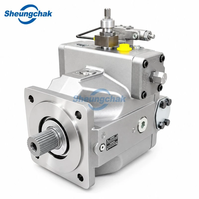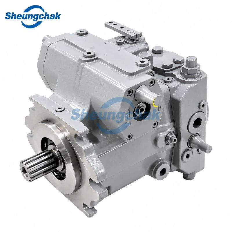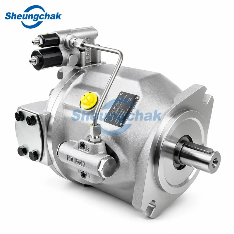

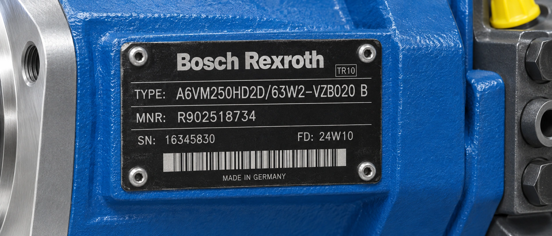
A Bosch Rexroth A6VM model code describes how one motor was configured when it left the factory: size, control device, shaft, flange, port plate, valves and sensors. It does not describe everything that was set on that motor. It is also not a statement that two motors with similar codes will behave the same way in your machine.
Each of the three A6VM datasheets used in this guide gives the same instruction: request a binding installation drawing before you finalise a design (RE-E 91604/05.2016, RE 91607/06.2016, RE 91610/07.09). The series 63 sheet adds that the relevant technical data must be specified in addition to the code when ordering.
Rexroth calls this string the type code in the European series 63 datasheet and the ordering code in the series 65 and 71 datasheets; both mean the same string. This guide covers three things:
- how to read the code;
- where the layouts differ between series;
- which fields you need to confirm before a replacement quote is worth anything.
Find the series number before you decode anything
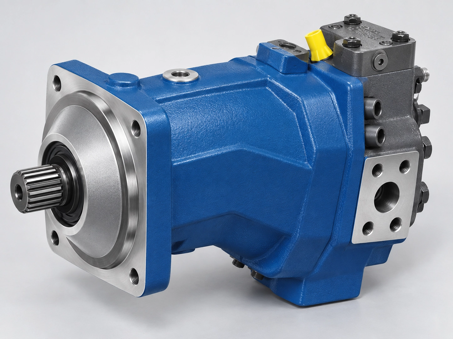
The A6VM is not one code table. Each series has its own datasheet, its own position count and its own letters for the same function. Decoding a series 65 plate against the series 63 table will give you a wrong answer at almost every position after the size.
| Series | Sizes covered | Pressure (nominal / max) | Datasheet used here |
|---|---|---|---|
| 63 | 28, 250, 355, 500, 1000 | 400 / 450 bar (size 28); 350 / 400 bar (250–1000) | RE-E 91604/05.2016 |
| 65 | 055–200 | 400 / 450 bar | RE 91607/06.2016 |
| 71 | 060–280 | 450 / 500 bar | RE 91610/07.09 |
| 63 (older, Americas) | 28–1000 in one sheet | 400 / 450 bar for 28–200 except size 80 at 350 / 400 bar; 350 / 400 bar for 250–1000 | RA 91604/02.04 |
Two cautions apply to this table.
The ranges belong to a datasheet edition, not to the product for all time. The current Bosch Rexroth product family page lists different size and pressure boundaries than the editions above, including a higher maximum pressure class (Bosch Rexroth product family page, viewed 2026-09-18). Always read the edition number printed on the sheet you are holding. For example, RE-E 91604/05.2016 means edition 05.2016, which replaces 06.2012.
The size numbers do not line up across series. Series 71 uses sizes 060, 085, 115, 150, 170, 215 and 280 (Bosch Rexroth, RE 91610/07.09). An A6VM115 is not a series 71 label for an A6VM107. Treating displacement as an equivalence test is how mismatched units get ordered.
Where the series number sits in each layout
Series 63. The series number appears after the control device, in the middle of the string: A6VM...HD1/63W-VZB020.... Everything after /63W- is mechanical and accessory configuration.
Series 65. More positions come before the series number: pressure control/override, solenoid connector, neutral position switch, additional function, response time damping and displacement setting each have a position of their own. The string therefore looks like A6VM...HA1T30004A/65MWV0.... After /65 come, in order:
- M: metric port and fastening threads with O-ring sealing to ISO 6149
- direction of rotation
- seal
- bearing
- flange
- shaft
- working port
- valve
- sensor
- the standard/special version position
Series 71. Series 71 follows the same overall arrangement, with /71 in that place.
So the practical rule is: find the two digits immediately after the slash. That is your series, and it tells you which datasheet to open.
Why an older A6VM107…/63W plate is not an error
If you are holding a size 107 or size 80 motor with 63 in the code, it is not a misprint. The earlier Americas datasheet RA 91604/02.04 covered sizes 28 through 1000 in a single series 63 table, including 55, 80, 107, 140, 160 and 200 (Bosch Rexroth, RA 91604/02.04). In the 2016-edition sheets, those mid sizes appear under series 65.
The most reasonable reading is that the range was reorganised between editions, not that the plate is wrong. That is our inference from comparing the two editions; Rexroth does not state it in either document. For a motor with an older code, decode against the edition that actually lists that size.
The older sheet also carries a pressure exception worth remembering. Within sizes 28–200 it rates size 80 at 350 bar nominal / 400 bar maximum, while the rest of that range is 400 / 450 bar.
A6VM model code decoded position by position
The table below follows the series 63 layout of RE-E 91604/05.2016, which runs to 20 positions. Whether a given option is available depends on the size: the datasheet marks each option per size column, and a letter that is valid for size 250 may not exist for size 28.
| Pos. | Field | Codes in this edition |
|---|---|---|
| 01 | Hydraulic fluid | no code = mineral oil / HFD; E = HFB, HFC (sizes 250–1000, long-life bearing only) |
| 02 | Axial piston unit | A6V - bent-axis design, variable |
| 03 | Drive shaft bearing | no code = standard; L = long-life (sizes 250–1000) |
| 04 | Operating mode | M = motor |
| 05 | Size (NG) | 28, 250, 355, 500, 1000 |
| 06 | Control device | HD1 HD2 HD3 EP1 EP2 HZ HZ1 EZ1 EZ2 HA1 HA2 DA DA1–DA6 |
| 07 | Pressure control / override (HD, EP only) | no code = none; D fixed setting; E hydraulic two-point override; G remote, proportional |
| 08 | Override for HA1 / HA2 | no code = none; T hydraulic remote; U1 U2 electric two-point; R1 R2 electric + travel direction valve |
| 09 | Series | 63 |
| 10 | Direction of rotation | W = bidirectional, viewed on drive shaft |
| 11 | Setting range for displacement | size 28: no code; sizes 250–1000: 1 or 2 |
| 12 | Sealing material | V = FKM |
| 13 | Drive shaft | A Z = splined DIN 5480; P = parallel keyed DIN 6885 |
| 14 | Mounting flange | B = ISO 3019-2 4-hole; H = ISO 3019-2 8-hole |
| 15 | Port plate + valve | 010 017 020 027 150 380 388 |
| 16 | Speed sensor | 0 none; F / H prepared for / mounted HDD; U / V prepared for / mounted DSM/DSA |
| 17 | Swivel angle sensor | no code = none; V optical; E electric |
| 18 | Connector for solenoids | 0 none (hydraulic control); P DEUTSCH moulded 2-pin; HIRSCHMANN on sizes 250–1000 |
| 19 | Beginning of control | A = at Vg min (standard for HA); B = at Vg max (standard for HD, HZ, EP, EZ, DA) |
| 20 | Standard / special version | no code = standard; -Y installation variants; -S special version |
Size, control and override
Position 05 is the size designation, which corresponds to maximum geometric displacement per revolution: size 250 is 250 cm³/rev, and size 1000 is 1000 cm³/rev.
Position 06 is where most of the functional character of the motor lives. The letters there are families rather than single options:
- HD - proportional hydraulic control. Control begins at Vg max, and rising pilot pressure at port X swivels the motor towards Vg min. HD1, HD2 and HD3 differ by the pilot pressure increase across the control range: 10, 25 and 35 bar respectively. HD3 is listed for sizes 250–1000 only.
- EP - proportional electric control, 12 V (EP1) or 24 V (EP2). It also begins at Vg max.
- HZ / EZ - two-point hydraulic / electric control: Vg min or Vg max, nothing in between.
- HA - automatic control related to high pressure. The controller reads working pressure internally and swivels the motor from Vg min towards Vg max as pressure rises. HA1 responds to a pressure increase of roughly 10 bar, HA2 to about 100 bar.
- DA - automatic control related to speed, intended to work with an A4VG pump with DA control.
Positions 07 and 08 are the override letters, and they attach to different control families:
- position 07 (D, E, G) applies only to HD and EP;
- position 08 (T, U1, U2, R1, R2) applies only to HA1 and HA2.
If a code shows an override letter that does not belong to its control family, treat the code as mis-transcribed rather than as an exotic variant.
The datasheet states one safety condition directly, and it travels with position 19: controls with beginning of control at Vg min (HA as standard) are not permissible for winch drives.
Shaft, flange and port plate: where SAE and metric split
This part of the code decides whether the replacement physically bolts up. It is also where the two interface standards diverge.
In the Americas datasheet RA 91604/02.04, the prefix itself carries the distinction: AA6V is the SAE version and A6V the ISO version. The consequences run through three positions:
| Interface | SAE version (AA6VM) | ISO / metric version (A6VM) |
|---|---|---|
| Drive shaft | S - SAE splined shaft, ANSI B92.1a | A / Z splined DIN 5480; P parallel keyed DIN 6885 |
| Mounting flange | C SAE J744 2-bolt; D SAE J744 4-bolt | B ISO 3019-2 4-bolt; H ISO 3019-2 8-bolt |
| Port plate | 510 517 520 527 (UN threads) | 010 017 020 027 150 (metric threads) |
Two qualifications keep this table from being over-read.
"Metric" describes the threads, not the port pattern. In both RE-E 91604/05.2016 and RE 91607/06.2016, the working ports are SAE J518 flange ports; only the fastening threads are metric.
The prefix rule belongs to the RA 91604/02.04 layout. In series 65 and 71, SAE splined shafts to ANSI B92.1a are ordinary options inside an A6VM code. RE 91607/06.2016 lists S7, T1 and T2 alongside DIN 5480 splines. On those codes, read the shaft position, not the prefix.
Read the port plate number as two pieces of information at once:
- The first two digits give where the working ports sit. 01 / 51 means ports A and B at the rear, 02 / 52 lateral and opposite, and 15 lateral plus rear.
- The third digit gives the valve. 0 means no valve, 7 a mounted flushing and boost-pressure valve, and 8 a mounted counterbalance valve.
So 027 is a lateral port plate with a flushing and boost-pressure valve, and 020 is the same plate without it. A motor quoted as "020" is not interchangeable with a "027" installation that depends on case flushing.
Series 65 handles the same information differently (Bosch Rexroth, RE 91607/06.2016):
- the thread configuration has a position of its own (M = metric, ISO 6149);
- the flange is coded M4 through S4 by ISO 3019-2 size;
- the working port and the valve are two separate positions, not one three-digit block;
- the valve position also encodes the flushing flow in l/min (A = 3.5, D = 10, G = 17, and so on).
If you are used to reading three-digit port plates, this is the position where a series 65 code will mislead you.
If the motor you are matching is an SAE-interface unit, the AA6VM page lists the SAE-version configurations we supply.
Valves, sensors and the version suffix
Positions 16 and 17 tell you whether the unit was built for a speed sensor or a swivel angle sensor, and whether the sensor was mounted at the factory or only prepared for. "Prepared for" means a spline and a plugged port, not a sensor. A replacement coded U will not produce a speed signal on arrival.
Position 20 is the one that ends a decoding exercise:
- -Y means a standard version with installation variants, for example T ports open and closed contrary to standard.
- -S means a special version.
Neither can be reconstructed from the ordering table, because the table describes what the letters are, not what was changed.
Series 71 uses its own suffix set: -0 standard, -K with attachment part, -S special version, and -T special version with attachment part. Its datasheet also notes that a short designation X refers to a special version not covered by the ordering code.
If the plate ends in -S, -Y, -T or X, stop decoding and ask for the original installation drawing or the material number record. Anything else is a guess.
How series 65 and 71 codes differ
Series 65 and 71 use a different layout from series 63, and the control letters changed with it. The table sets out what each datasheet lists. It shows where a function is coded; it does not say that units from different series are interchangeable.
| Function | Series 63 (RE-E 91604/05.2016) | Series 65 (RE 91607/06.2016) | Series 71 (RE 91610/07.09) |
|---|---|---|---|
| Positions in the code | 20 | 21 | 21 |
| Proportional hydraulic | HD1 HD2 HD3 - begins at Vg max | HP1 HP2 positive (begins at Vg min); HP5 HP6 negative (begins at Vg max) | HP1 HP2 positive; HP5 HP6 negative |
| Proportional electric | EP1 EP2 - begins at Vg max | EP1 EP2 positive; EP5 EP6 negative | EP1 EP2 positive; EP5 EP6 negative |
| Two-point hydraulic | HZ (250–1000), HZ1 (28) | HZ5 (140–200), HZ7 (55–107), negative | HZ5 (150–215), HZ7 (60–115), negative |
| Two-point electric | EZ1 EZ2 | EZ5 EZ6 (140–200), EZ7 EZ8 (55–107), negative | EZ5 EZ6 (150–215), EZ7 EZ8 (60–115), negative |
| Automatic, high-pressure related | HA1 HA2 - begins at Vg min | HA1 HA2, positive | HA1 HA2, positive |
| Automatic, speed related | DA (250–1000), DA1–DA6 (28) | DA0 DA1 DA2, negative | DA0 DA1 DA2, negative (DA1 DA2 not for size 280) |
| Where beginning of control is coded | Separate position 19: A / B | Built into the control letter | Built into the control letter |
| Pressure control / override | Position 07 (D E G) and position 08 (T U1 U2 R1 R2) | One position: 00, D1 (HP5, HP6, EP5, EP6 only), T3, U1, U2, R1, R2 | Same set as series 65 |
| Displacement setting | 1 / 2 band (250–1000); no code for size 28 | Setting-screw codes A–M | A, B, E, F only |
| Response time damping | Not a code position; described per control and size (size 28: specify when ordering) | Position 09: 0 1 4 7 | Position 09: 0 1 4 7 |
| Version suffix | -Y, -S | Y, S | -0, -K, -S, -T; X outside the code |
The table leads to four reading rules.
The digit is not a family link across series. Series 63 codes the beginning of control in a position of its own. In series 65 and 71 it is part of the control letter:
- positive controls (HP1, HP2, EP1, EP2) begin at Vg min;
- negative controls (HP5, HP6, EP5, EP6) begin at Vg max.
So a series 63 HD1 and a series 65 HP1 run in opposite directions. The HD1 begins at Vg max and reduces displacement as pilot pressure rises. The HP1 begins at Vg min and increases displacement as pilot pressure rises.
The winch-drive restriction follows the beginning of control, not the letter HA. Both the series 63 and the series 65 sheets state that controls with beginning of control at Vg min are not permissible for winch drives, and both name HA as the example. In series 65, the positive controls HP1, HP2, EP1 and EP2 also begin at Vg min. The winch-drive ordering example in RE 91607/06.2016 uses HP5D1, which is a negative control.
The same letter does not mean the same setting range. HP2 in RE 91607/06.2016 has a beginning-of-control setting range of 5–35 bar. HP2 in RE 91610/07.09 lists 5–50 bar. Both editions give a standard setting of 10 bar.
Setting-screw letters are not setting values. In series 65, each letter from A to M combines two things: a Vg max setting screw (none, short or medium) and a Vg min setting screw (short to extra long). Each letter maps to a displacement band that differs by size. Series 71 lists only A, B, E and F. Both sheets still ask for the exact Vg min and Vg max in plain text:
- RE 91607/06.2016 warns that settings not listed in its table may lead to damage;
- RE 91610/07.09 states that its maximum settings must not be exceeded.
A worked example from the series 65 datasheet
RE 91607/06.2016 prints a complete ordering code in its counterbalance valve section: A6VM080HA1T30004A/65MWV0N4S97W0-0. It is ordered together with a separately coded counterbalance valve, BVD20F27S/41B–V03K16D0400S12. This is a datasheet example, not a nameplate, but it shows the 21-position layout in full.
| Pos. | Code | Meaning in RE 91607/06.2016 |
|---|---|---|
| 01–02 | A6V M | Bent-axis variable unit, motor |
| 03 | 080 | Size 80 |
| 04 | HA1 | Automatic control related to high pressure, positive, pressure increase ≤ approx. 10 bar |
| 05 | T3 | Override, hydraulic remote control, proportional |
| 06 | 0 | No solenoid connector (hydraulic control) |
| 07 | 0 | No neutral position switch |
| 08 | 0 | No additional function |
| 09 | 4 | Damping one-sided in inlet to large stroking chamber (HA) |
| 10 | A | No Vg max setting screw; short Vg min screw (adjustable to 0) |
| 11 | 65 | Series |
| 12 | M | Metric port threads, ISO 6149 |
| 13 | W | Bidirectional |
| 14 | V | FKM seals |
| 15 | 0 | Standard bearing |
| 16 | N4 | ISO 3019-2 140-4 flange |
| 17 | S9 | See note below |
| 18 | 7 | Port plate with pressure relief valves for mounting a BVD20 counterbalance valve |
| 19 | W | Counterbalance valve BVD/BVE mounted |
| 20 | 0 | No speed sensor |
| 21 | 0 | Standard version |
Position 17 is the useful lesson. S9 does not appear in the drive shaft table of the same edition, which lists S7, Z8 and Z9 for size 80. A code copied from any source, including a datasheet example, still has to be checked against the table for its edition and against the installation drawing.
Positions 18 and 19 teach a second point. The counterbalance valve is a separate product with its own ordering code; the motor code only records that one is mounted.
What the model code does not tell you
This section matters most for replacement. It explains why two motors with the same code can behave differently on the machine.
The exact displacement settings are specified in plain text, not in the code. The series 63 setting-range position tells you only which band the unit falls in:
- 1 = Vg min from 0 to 0.4 Vg max;
- 2 = Vg min above 0.4 to 0.8 Vg max.
The actual values are stated separately, and the datasheet instructs the buyer: "Please specify exact settings for Vg min and Vg max in plain text when ordering." Where no setting code is given for sizes 250 to 1000, the standard setting is Vg min = 0.2 × Vg max. Series 65 uses setting-screw codes A through M and repeats the same instruction, adding a warning that settings outside the tabulated combinations may lead to damage.
The beginning of control is also specified in plain text. Position 19 tells you only whether control begins at Vg min or Vg max. The actual pressure or pilot pressure at which it begins is a written instruction.
For HD controls, the datasheet gives a generic ordering example: "beginning of control at 10 bar." The standard settings differ by variant:
- HD1: 3 bar, within a 2–20 bar setting range;
- HD2 and HD3: 10 bar.
For HA controls the example is "beginning of control at 300 bar", within an 80–350 bar range for HA1 on size 28. Two motors both coded HA1 can start swivelling hundreds of bar apart.
Case pressure shifts that beginning of control. In series 63 the effect depends on size as well as on control:
| Series 63 size | Beginning of control raised by higher case pressure | Lowered | No effect |
|---|---|---|---|
| 28 | HD, HA.T | DA | EP, HA, HA.R, HA.U |
| 250–1000 | HD, EP, HA, HA.T | DA | - |
Factory settings are made at a defined case pressure: 2 bar absolute for size 28 and 1 bar absolute for sizes 250 to 1000. An installation with a different case pressure will therefore not reproduce the bench behaviour exactly.
Series 65 lists the effect as follows:
- raised: HP and HA.T3;
- lowered: DA;
- unaffected: EP, HA, HA.R and HA.U;
- factory settings made at 2 bar absolute.
RE 91610/07.09 gives the same list for series 71 but limits the HA.R / HA.U exemption to sizes 60 to 215.
Response time damping is not always visible either. In series 65 it has its own position (0, 1, 4, 7). In series 63 the throttle pin or orifice is described in each control section as standard or optional per control and size. For size 28 the datasheet notes that response time damping must be specified when ordering. The same code can therefore come with different pivot behaviour and a different machine response.
Replacement matching checklist
Before a replacement quote can be evaluated, the following fields need to be on the table. The first block comes off the plate. The second block does not exist on the plate: it has to come from the original order, from the machine OEM, or from a measurement on the removed unit.
From the code string:
- Series (the two digits after the slash) and the datasheet edition you decoded against
- Size
- Control device, including (in series 65 and 71) whether it is positive or negative control, and any override letters
- Direction of rotation and sealing material
- Drive shaft code, and whether it is DIN 5480, DIN 6885 or an SAE spline
- Mounting flange code and standard (ISO 3019-2 or SAE J744)
- Port plate: port arrangement, thread type (metric or UN), and the valve digit or valve position
- Speed sensor and swivel angle sensor: none, prepared for, or mounted
- Connector type, if the control has a solenoid
- Beginning of control at Vg min or Vg max (series 63 position 19; part of the control letter in series 65 and 71)
- Any -Y, -S, -K, -T or X suffix
Not in the code string:
- Vg min and Vg max as actually set, in cm³/rev
- Beginning of control setting in bar, plus the second pressure setting where a D / E / G, D1 or T / T3 override is fitted
- Response time damping: throttle pin or orifice
- The counterbalance valve's own ordering code, if the motor has one mounted
- Material number (MNR), if you have it. The MNR and the type code are two different identifiers, and the MNR is the one that resolves a -S version.
- Photographs of the full nameplate and of the port face
We also recommend asking any supplier, including us, to state three things in writing: which manufacturer's product is being quoted, the full configuration, and the installation drawing. If you are decoding a Rexroth pump code rather than a motor, the same method applies in our A4VSO model code guide.
Send the code for a configuration check
If you have the plate but not the settings, which is the normal situation, send the following through our inquiry form:
- the full code string;
- the size;
- photographs of the nameplate and the port face.
We will tell you:
- which datasheet edition the code decodes against;
- which fields are still missing for a like-for-like match;
- which of those fields have to come from the machine rather than from us.
Where a field cannot be established from the code, we will say so rather than assume it.
Frequently asked questions
Is A6VM the same as AA6VM?
They are the same motor family in different interface versions. In the Americas datasheet RA 91604/02.04, AA6V denotes the SAE version and A6V the ISO version, and the difference runs through the shaft, the mounting flange and the port plate numbering - SAE port plates are numbered 510/517/520/527 with UN threads, the metric ones 010/017/020/027 with metric threads. That prefix rule belongs to the RA 91604/02.04 layout: in series 65 and 71 codes, SAE splined shafts are regular options inside an A6VM code, so read the shaft, flange and port positions rather than the prefix.
Does the A6VM model code include the minimum displacement setting?
No. The code gives a setting range or setting-screw code only. The series 63, 65 and 71 datasheets all instruct the buyer to state Vg min and Vg max in plain text when ordering. Where no setting code is present for series 63 sizes 250 to 1000, the standard setting is Vg min = 0.2 × Vg max.
Can a series 65 A6VM replace a series 63 unit?
That cannot be answered from the codes. The two series use different position layouts, different control letters and different size numbering, and series 65 builds positive or negative control into the control letter where series 63 uses a separate beginning-of-control position. A matching-looking code is not evidence of a matching motor. Compare installation drawings for shaft, flange, ports and overall dimensions, and confirm the control settings separately. We do not publish interchangeability conclusions.
What does -S at the end of a code mean?
Special version. The ordering table defines the letter but not the deviation, so a -S unit cannot be reconstructed from the code alone - you need the original installation drawing or the material number. The same applies to the series 71 suffix -T and to the short designation X.
About the references in this guide
Rexroth is a trademark of Bosch Rexroth AG. This guide interprets publicly available Bosch Rexroth datasheets. The references to Rexroth codes and documents do not establish the manufacturer, authorization status or interchangeability of any product offered by another supplier, including products offered by us.
Sources
- Bosch Rexroth, Axial piston variable motor A6VM Series 63, RE-E 91604, edition 05.2016 - PDF
- Bosch Rexroth, Axial piston variable motor A6VM series 65, RE 91607, edition 06.2016 - PDF
- Bosch Rexroth, Axial Piston Variable Motor A6VM, Series 71, RE 91610/07.09 - PDF
- Bosch Rexroth, Axial Piston Variable Displacement Motor AA6VM (A6VM), Sizes 28 to 1000, Series 6, RA 91 604/02.04 - PDF
- Bosch Rexroth, Axial piston variable motors for mobile machines (product family page), viewed 2026-09-18 - Link