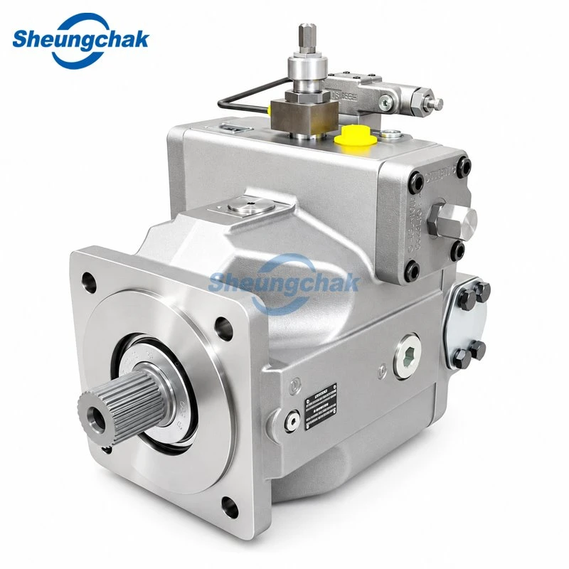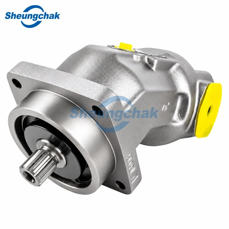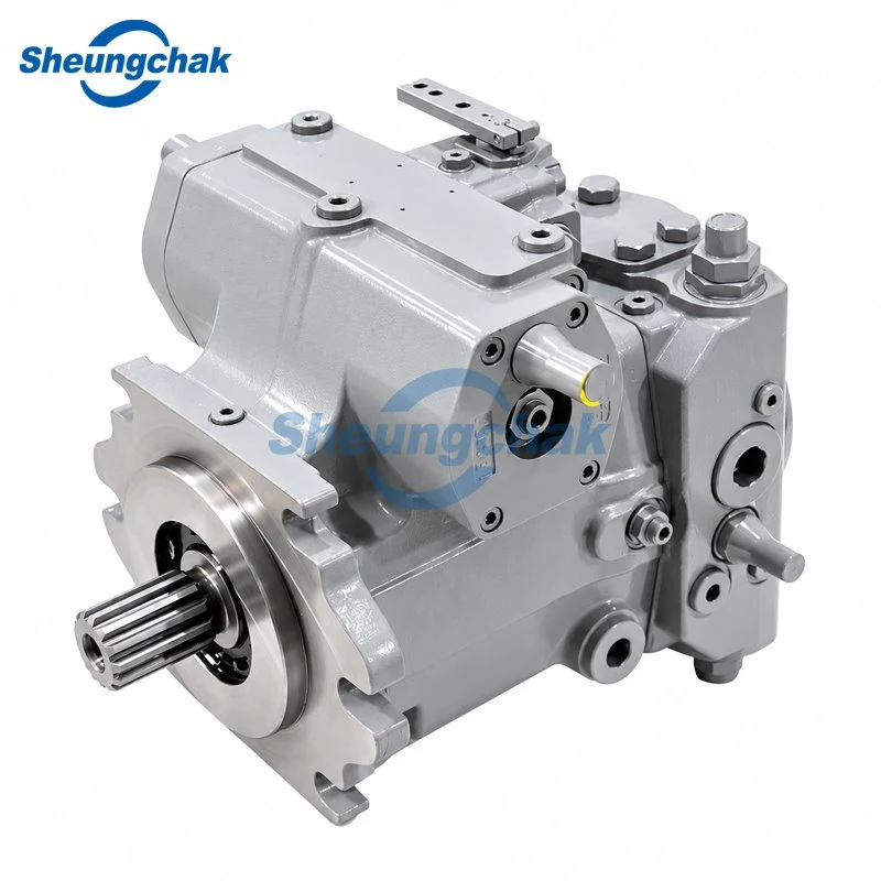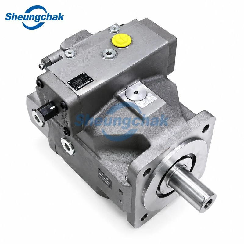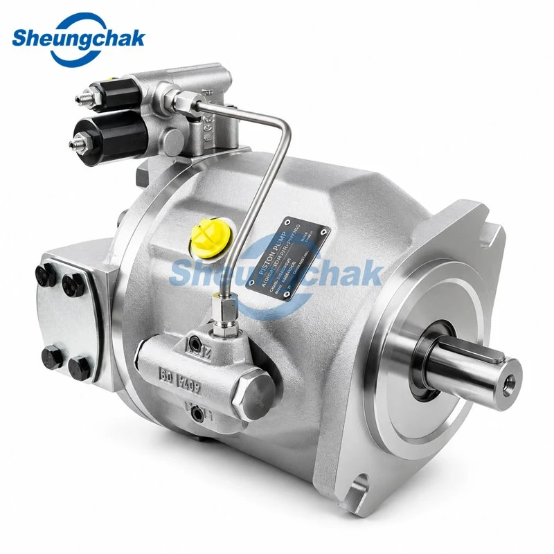

Excessive case drain on a hydraulic pump can indicate a worn rotating group, additional oil entering the case from another source, or a measurement taken under conditions that make the reading misleading. Before deciding that the pump needs repair, record pressure, speed, oil temperature and control state, then compare the result with the correct model-specific baseline.
Start with the manufacturer's case-drain data and test procedure. Where those are unavailable, a repeatable operating history can help identify change. A rule of thumb is a screening tool, not a replacement or overhaul criterion.
What case drain flow is and why a healthy pump has it
A healthy piston pump can have internal leakage and other designed flows entering its housing. The case drain carries this oil away while the installation maintains the required housing oil level and pressure.
For a swashplate axial piston pump, the relevant interfaces include:
Cylinder block and valve plate: leakage can pass toward the housing or between pressure regions, depending on the sealing surfaces and damage location.
Slippers and swashplate: oil supplied to hydrostatically supported slippers provides lubrication; some escapes into the housing.
Pistons and cylinder bores: clearance between the moving parts provides another possible leakage path.
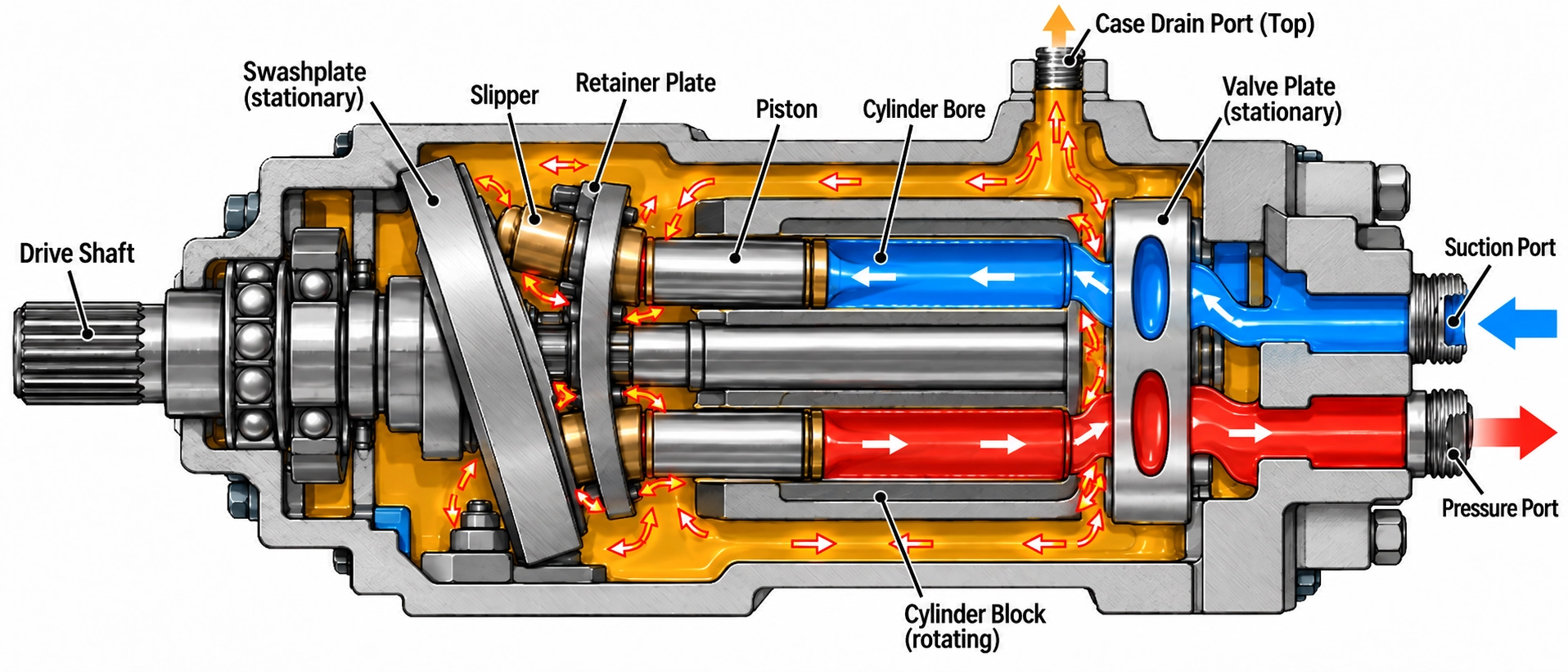
Control oil, charge-relief discharge or external drain flows may also enter the housing, depending on the design.
This distinction matters: measured case drain is not automatically the pump's total volumetric loss. Some internal leakage may return to a lower-pressure working region, while some measured drain oil may originate outside the rotating group. An efficiency curve therefore cannot always be converted directly into a case-drain limit.
Keep the housing filled as required by the manufacturer. Do not reroute the drain to suction, change drain ports or combine drains without checking the approved installation arrangement.
How much case drain flow is "excessive"?
There is no universal acceptable flow in L/min, gpm or percentage of pump capacity. A useful comparison must identify the pump, circuit, test conditions and the flows included in the measurement.
| Reference | Appropriate use | Important limitation |
|---|---|---|
| OEM case-drain specification or curve | Compare the exact pump at the stated operating conditions | Check model, control configuration and measurement location |
| OEM volumetric-efficiency data | Evaluate delivered flow under the prescribed test conditions | Not necessarily interchangeable with case-drain flow |
| A verified baseline from the same installation | Identify changes during repeatable tests | Confirm that the original condition and measurement were valid |
| A published rule of thumb | Flag a result for further investigation | Does not establish a universal repair or rejection limit |
The five-plus-five example
Sergiy Sydorenko's five-plus-five method is an attributed field estimate for certain medium-size, open-circuit variable axial piston pumps. It does not apply to pumps with built-in flushing, a pilot pump discharging into the housing, or an internal connection between the housing and the suction line.
The arithmetic is:
Theoretical flow (L/min) = displacement (cm³/rev) × speed (rpm) ÷ 1,000
For the author's illustrative pump:
Displacement: 100 cm³/rev
Assumed rated speed: 2,200 rpm
Theoretical nominal flow: 220 L/min
Five percent: 11 L/min
Ten percent: 22 L/min
These are calculated reference figures, not measured acceptance results. The original method assumes rated pressure, rated speed and the specified oil viscosity, with the pump not destroking. This example includes no additional control-flow allowance; known control flows must be accounted for separately. These assumptions do not authorize operation outside the exact pump's approved limits.
Use an elevated result to justify further diagnosis. Do not order an overhaul solely because a reading reaches 11 or 22 L/min, and do not clear a pump solely because it falls below those figures. The original five-plus-five method is explicitly a rough alarm tool.
Test conditions that change the reading
Pressure and speed must both be recorded. Leakage is pressure-sensitive, but speed remains relevant to pump operation and to any percentage based on theoretical flow. Comparing a low-speed reading with a rated-speed percentage can distort the interpretation.
Temperature must be considered together with viscosity. Match the fluid and viscosity conditions required by the test procedure. "Warm oil" is not a sufficiently precise comparison condition.
Displacement and control state must be identified. On-stroke operation, pressure-compensated destroking and load-sensing standby are different conditions. A change between them can alter the reading without proving wear.
Choose conditions for the test's purpose. An on-stroke screening method and an OEM-approved standby or condition-monitoring test may use different operating points. Each needs its own baseline. An unloaded measurement may help establish a repeatable observation, but it cannot by itself establish loaded performance.
Never increase pressure or speed beyond the approved operating envelope simply to match a published example.
How to measure case drain flow safely
Case-drain testing should be performed by trained personnel using the equipment manufacturer's and pump manufacturer's procedures. The principles below do not replace the machine-specific service instructions.
Before changing connections:
Shut down and isolate the machine according to the site procedure.
Release stored hydraulic energy and verify the required safe condition.
Identify the correct drain port and every flow entering the proposed measurement point.
Confirm suitable instruments, hoses, fittings, collection capacity and pressure protection.
Define operating limits and stop conditions before restarting.
Do not loosen a connection under pressure, search for leaks by hand or touch a drain hose to judge temperature. Use suitable temperature instruments. Never bypass pressure protection or improvise a blocked main outlet to obtain a test reading.
Inline flow measurement
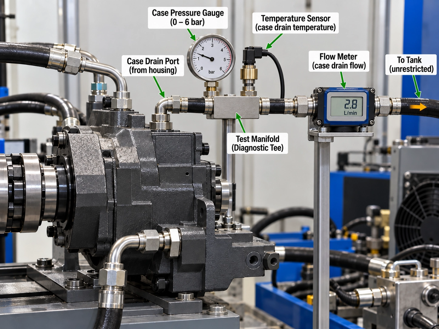
Use a calibrated meter suitable for the expected flow, fluid, temperature and installation. Its pressure drop, together with the hoses and fittings, must remain compatible with the pump's case-pressure limit.
Maintain an unrestricted, approved drain route throughout the test. Monitor case pressure, flow and oil temperature, and record working pressure and shaft speed at the same operating point. Use an OEM-approved measurement point that represents pump housing pressure, and record its position relative to the meter and drain-line restrictions. A reading taken only downstream of those restrictions does not establish the pressure in the housing.
Stop the test if case pressure or temperature approaches the approved limit, flow exceeds the equipment's capacity, leakage develops or machine behavior becomes unsafe. Isolate the system before correcting the setup.
Danfoss's M46 technical information, page 12, warns that operation outside charge- and case-pressure limits can damage the pump and calls for appropriately sized drain plumbing. This is a model-specific design reference, not a universal instrument specification.
Timed collection
Timed collection is an option only where the OEM or an approved test procedure permits it. It is not suitable for every installed system.
The assessed setup must maintain housing fill, continuous drainage and required reservoir or charge-supply conditions. Secure the discharge hose and provide suitable containment for hot oil. Account for the oil removed from the system and the available collection capacity. Never cap the pump's active drain or interrupt a drain required by another component.
Where timed collection is permitted:
Drain flow (L/min) = collected volume (L) × 60 ÷ collection time (s)
Restore and verify the approved drain arrangement after the test.
Test record template
| Field | Record |
|---|---|
| Identification | Date, operating hours, model code and serial number |
| Circuit | Open or closed circuit; measurement point |
| Working pressure | Outlet pressure; both loop pressures where required |
| Speed | Measured shaft rpm |
| Displacement | Setting or known operating state |
| Control | Control type, settings, on-stroke, destroking or standby |
| Fluid | Fluid type, ISO VG and measured temperature |
| Drain flow | L/min or US gpm; measurement method |
| Case pressure | Value, unit, measurement point and reference: gauge, absolute or differential |
| Charge system, where applicable | Charge pressure, unit, measurement point and pressure reference; relevant control and flushing state |
| Instruments | Identification, range and calibration status |
| Included flows | Control, flushing, charge-relief or other component drains |
| Observations | Noise, temperature changes, seal leakage and oil condition |
Use one record for each operating point. Keep pressure references consistent between measurements and specifications.
High drain flow that does not necessarily indicate wear
Trace the circuit before attributing an elevated reading to damaged clearances. Designed flows can increase case drain, and faults elsewhere in the system can change those flows.
| Source or operating state | Why the reading can rise | Diagnostic check |
|---|---|---|
| Pressure-compensator operation | Control behavior and destroking can change case flow | Compare the same approved control state |
| Load-sensing standby | Standby flow can differ from loaded, on-stroke flow | Use a baseline for that operating point |
| Torque limiter or LS bleed | The control arrangement may contribute drain flow | Check the exact control schematic |
| Pilot supply or pilot-valve drains | Oil may discharge into the pump housing | Identify the source before evaluating rotating-group leakage |
| Charge-relief discharge | Excess charge flow may enter the housing | Follow the closed-circuit pump's procedure |
| Loop flushing | Flushing introduces another flow path | Establish where the flushing oil actually drains |
| Another component draining through the housing | The measured oil includes more than pump leakage | Trace the approved interconnections |
| A shared drain downstream | The meter includes other components' drains | Identify each contribution without obstructing required drainage |
The Danfoss M46 technical information (pages 16 and 34) illustrates charge-relief discharge into the housing and specific tandem-pump drain arrangements. Its flushing guidance also requires sufficient charge supply. These examples show why closed-circuit readings need circuit-specific interpretation.
Do not disconnect charge, flushing or control flows simply to make a drain reading smaller. Any isolation test must be permitted by the approved procedure.
Wear causes behind excessive case drain
Once the test is valid and other flows are accounted for, an increase above the appropriate baseline can support a wear diagnosis. It still needs corroborating evidence.
Valve plate and cylinder block face. Damage to sealing surfaces can increase leakage toward the case, between pressure regions, or both. The resulting output loss will not necessarily appear entirely at the drain port.
Slipper interfaces. Damage at a hydrostatically supported slipper can disturb its lubricating film and change leakage. Assessment requires inspection of the mating surfaces and support arrangement.
Pistons and bores. Enlarged or damaged clearances can increase leakage. Confirm the condition through the applicable inspection and dimensional checks.
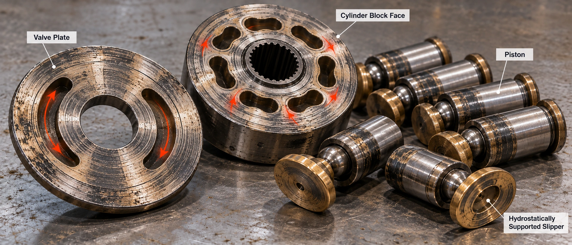
Use drain flow alongside delivered flow, working pressure, case pressure, temperature, noise and oil condition. A normal drain reading does not exclude a control, inlet, mechanical or other pump fault.
If wear is confirmed, investigate contamination, inlet conditions, fluid condition, overheating and installation issues before returning a repaired or replacement pump to service. Replacing damaged parts does not remove the cause of their damage.
When case pressure, not flow, is the problem
High case-drain flow and high case pressure are different findings. Normal flow through a restricted drain can produce excessive pressure; elevated flow through an adequately designed route may remain within the allowed pressure.
Repeated shaft-seal leakage warrants a case-pressure check, not just another seal replacement.
Use the correct pressure reference
Read the exact pump's limits and installation instructions. Distinguish:
Gauge pressure: pressure relative to local atmospheric pressure.
Absolute pressure: pressure relative to vacuum.
Differential pressure: pressure relative to another specified port or location.
Do not compare unlike references or apply another model's continuous or cold-start limit.
If measured case pressure exceeds the permitted condition, stop the test. After isolation, investigate restrictions and assess whether the event has already damaged seals or internal components.
Drain arrangement checks
- Confirm the specified drain port and mounting arrangement maintain housing fill.
- Check hose size, fittings, routing and reservoir connection against the approved installation.
- Inspect for kinks, obstruction, damaged hoses or unintended shutoff points.
- Include any meter, cooler, filter and shared-line flow in the back-pressure assessment.
- Check conditions during cold start as well as warmed operation where required.
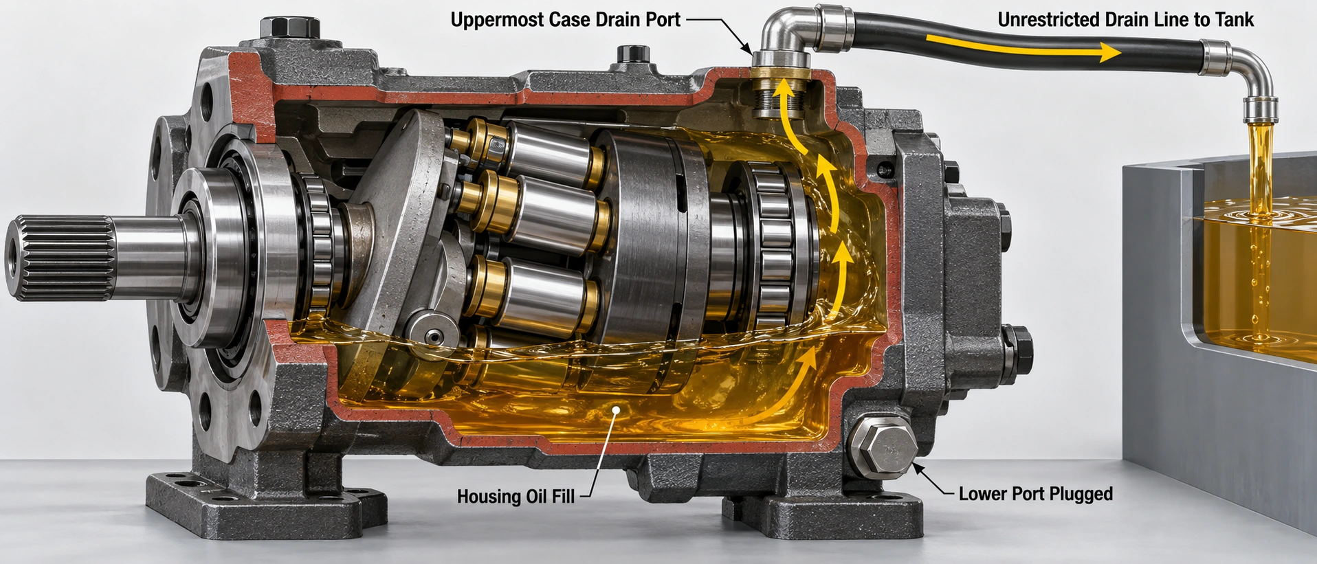
Do not add a conventional filter to a case drain without OEM approval. An engineered arrangement must account for pressure drop, contamination loading, cold oil, bypass behavior and the pump's limits. An arbitrary screen size is not a substitute for that assessment.
Where elevated case pressure affects a control referenced to the housing, control behavior may also change. The response depends on the control design; it is not identical across all compensators.
Trending vs one-off readings
A single valid measurement describes one operating point. Repeated measurements under comparable conditions can reveal a developing change.
Caterpillar's US5563351 patent describes evaluating pump wear using changes in case-drain flow. It documents a proposed monitoring method, not a universal repair threshold or proof of field effectiveness.
A 2025 TU Dresden conference paper combines case-drain evaluation with electrical power and temperature differences in a three-pump industrial installation. Its abstract identifies dead-head operation as a favorable monitoring condition in that study. That research condition must not be turned into an instruction to block an installed pump's outlet.
For maintenance planning:
Establish a documented baseline after the pump's condition has been verified.
Repeat the approved operating point, including pressure, speed, viscosity and control state.
Record instrument changes and any modification to control, charge, flushing or drain routing.
Set the inspection interval according to equipment criticality and observed change.
Investigate a sustained rise alongside other condition indicators.
If conditions change, establish whether the readings remain comparable before treating the difference as deterioration.
Repair or replace: making the call
Work through the evidence in order.
Validate the measurement. Confirm the procedure, instruments, operating conditions and included flows.
Check the correct baseline. Use OEM data first, then a verified installation history. Treat an experience-based estimate as a screening reference.
Account for non-wear flow. Review controls, charge relief, flushing and shared drains.
Resolve excessive case pressure. Stop testing if limits are exceeded. Correct the cause after isolation and assess existing damage.
Look for supporting evidence. Evaluate delivered flow, pressure capability, temperature, noise, fluid analysis and service history.
Inspect where justified. Use an approved teardown and inspection process to establish the extent of damage and available repair options.
If metal debris, severe noise, rapid overheating or loss of safe machine function is present, stop operation and follow the equipment's fault-response procedure. Do not continue running solely to collect a trend.
A repair-versus-replacement decision should consider the condition of the rotating group, mating surfaces, bearings and housing, together with repairability, parts availability and the required configuration. A single drain-flow percentage cannot settle that decision.
Before recommissioning, address contamination and the original failure mechanism using the equipment's cleaning, filtration and commissioning requirements.
If you decide to replace the pump
Start with exact identification and confirm the replacement specifications before ordering.
When requesting a quotation, provide:
- The complete model code and a clear nameplate photograph.
- The machine application and circuit type.
- Displacement, operating pressure, speed and control type.
- Rotation direction, mounting flange, shaft and port details.
- Drain-flow, case-pressure and oil-temperature records, including test conditions.
Ask about available configurations, documented specifications and a quotation. Confirm installation compatibility before ordering; similar appearance or displacement alone does not establish interchangeability.