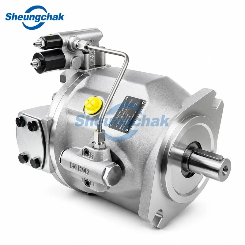

Hydraulic piston pump pressure loss can result from restricted inlet supply, insufficient drive speed, incorrect controls, external unloading or leakage, and internal pump wear. A low pressure reading alone does not identify which path is responsible-or establish that the pump needs replacement.
The useful distinction is whether the pump is receiving enough fluid and drive input, responding correctly to its controls, and delivering output into the intended circuit path. Investigate these conditions before attributing the complaint to the rotating group.
This article focuses on axial piston pumps. Its model-specific reference is the Danfoss Series 45 Frame K2 open-circuit service manual, April 2017. Other models and closed-circuit systems require their own documentation.
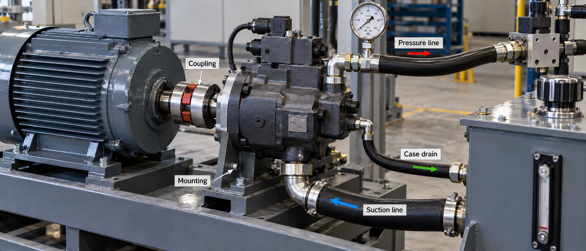
Safety: Follow the machine manufacturer's isolation, stored-energy and service procedures. Qualified personnel must use approved measurement methods. Relieve pressure before removing hoses, fittings, gauges or components, and never use a hand or another body part to locate a pressurized leak. Do not block a case-drain line or raise protective settings as an improvised diagnostic test. See the Danfoss safety instructions.
5
symptom patterns to compare
4
diagnostic branches: supply, drive, control and system
1
measurement record for technical review
0
universal drain-flow limits applied across pump models
Identify the Pressure-Loss Pattern Before Choosing a Cause
Describe the operating event first. "Pressure falls during lifting after warm-up" provides a more useful starting point than "the pump is weak." This table organizes candidate causes; it is a reporting aid, not a fault-confirmation chart.
| Observed pattern | Record first | Candidate causes / next evidence |
|---|---|---|
| Pressure is low at start-up | Actual and expected pressure, test point, shaft speed, temperature and commanded function. | Confirm expected response for that operating state; examine supply, rotation, control and unloading conditions. |
| Pressure falls during a loaded function | Function, load, pressure before and during event, speed and available flow readings. | Compare commanded demand with outlet flow and pressure. Low outlet flow directs attention to supply, drive and controls; adequate output shifts attention to downstream diversion, pressure loss or actuator leakage. |
| Performance deteriorates after warm-up | Paired temperature, speed, load and control-state readings. | Compare equivalent conditions; investigate viscosity-related leakage, changing supply conditions or control behavior. |
| Only one function is affected | Affected and unaffected functions, valve state and measurement locations. | Examine components and signal paths unique to that function; a shared pump fault remains possible. |
| Symptom began after maintenance | Work performed, parts changed, settings and commissioning records. | Compare original specification with installed unit and documented changes; investigate connections, supply, contamination and assembly. |
A reading taken in standby should not automatically be compared with a working-pressure target. First establish what the control and circuit should do in that state.
Check What the Pressure Reading Actually Represents
Identify the full pump model code, circuit type, measurement location, unit and pressure reference before comparing a reading with a specification.
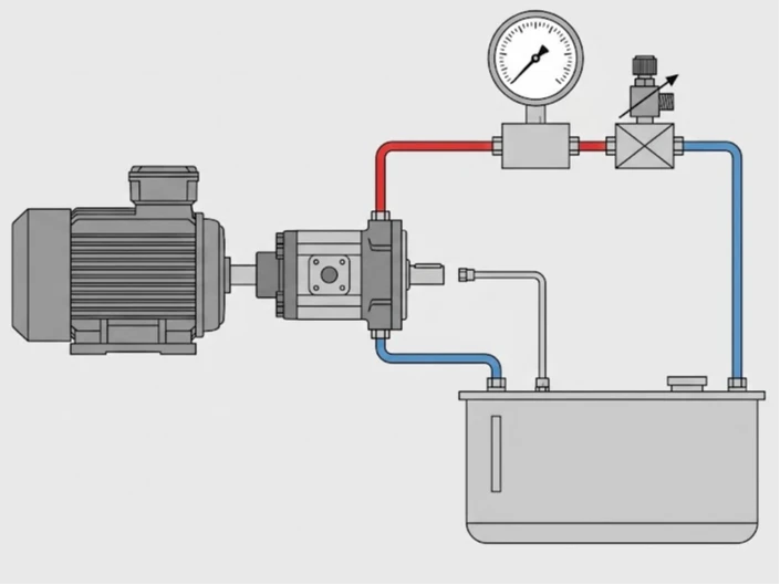
Pump Type, Test Point, and Pressure Reference
Use the machine schematic to establish whether a reading represents pump outlet pressure, actuator pressure, case pressure or a control signal. A difference between locations may reflect the intervening circuit rather than a defective pump.
For Series 45 K2, the pressure-compensator setting is referenced to case pressure. Danfoss specifies subtracting case pressure from system pressure to determine the actual setting. Keep measured system pressure, measured case pressure and calculated difference separate. This relationship is model-specific. See the K2 manual, printed page 23.
Record instrument range and calibration status, whether the reading is gauge, absolute or differential pressure, and whether compared readings were simultaneous. Use the document revision applicable to the installed pump.
Open-Circuit and Closed-Circuit Boundaries
Open-circuit investigations and closed-circuit hydrostatic investigations do not use interchangeable control assumptions or test procedures. A closed-circuit pump such as an A4VG requires review of its particular replenishment and control arrangement. Do not apply K2 PC settings, port identities or inlet limits to it. For that branch, see A4VG pressure-loss, noise and overheating symptoms, then use documentation for the actual series and machine.
Separate Supply, Drive, Control, and System Faults
Inlet Supply: Is the Pump Receiving Enough Fluid?
Restricted supply can limit pump filling and output. Investigate reservoir level, inlet restrictions, fluid condition and recent hose or filter work. Air ingress and cavitation require separate investigation; noise alone does not distinguish them. Use inlet measurements and fluid requirements for the installed model. A limit taken from another pump is not an acceptance criterion for this installation.
Mechanical Drive: Is the Expected Input Reaching the Pump?
Check whether recorded shaft speed and rotation agree with the installed configuration. Low speed can reduce available flow. Include the drive and coupling in the technical review rather than assuming that a running motor proves correct pump input.
PC and LS Controls: Is Output Being Limited or Commanded Incorrectly?
Pressure-compensator (PC) control regulates flow to maintain its pressure setting. Load-sensing (LS) control responds to demand through the pressure difference associated with a metering valve. Understand their operating states before interpreting low pressure.
For K2, troubleshooting tables identify low control settings, sticking or worn spools, contamination and an obstructed LS signal line as fault candidates. They also connect low output with inlet conditions, speed and rotation. These are investigation branches, not instructions to adjust controls. See the Danfoss K2 troubleshooting tables, printed pages 20–22.
For K2 LS control, neutral operation can produce standby pressure because the valve drains the LS signal. During a loaded command, an absent or inconsistent signal warrants investigation of the signal path; a verified signal with inadequate output warrants review of supply, drive and pump control. Reaching the PC setting can also cause normal de-stroking. None of these observations alone confirms wear. See the K2 control description, printed pages 12–13.
External Relief and Valving: Where Is the Flow Going?
A pump may be delivering flow while an unloading, relief or faulty valve path prevents the intended pressure response. Leakage elsewhere in the circuit can reduce the output available to a working function. Identify these paths on the machine schematic. A complaint affecting one function warrants examination of that function's components; a complaint affecting several functions warrants examination of shared supply and control paths.
Internal Wear: Is There Evidence Beyond Low Pressure?
Internal leakage can reduce useful delivered flow. However, a pressure complaint does not identify a damaged piston, cylinder block, valve plate or control component. Internal inspection becomes more justified when supply, drive, controls and external circuit conditions have been checked and a documented performance test still shows unacceptable output. Persistently deficient outlet flow together with leakage outside the applicable manufacturer criterion, under comparable conditions, strengthens the case for internal investigation. Without a valid criterion or comparable conditions, a drain-flow reading remains inconclusive.
Record Leakage Evidence Without Using a Universal Limit
Keep Case-Drain Flow and Case Pressure Separate
Case-drain flow is volume per unit time. Case pressure is pressure inside the housing. They answer different questions and need separate measurements. Some case-drain flow is expected because internal lubrication and cooling paths return fluid through the housing. Its presence alone does not establish failure. The original K2 reference describes this function in its general description.
A drain-flow measurement cannot account for every leakage path in the hydraulic system. Leakage through an actuator or external valve will not necessarily appear in the pump drain measurement. Depending on pump and circuit configuration, other return flows may contribute to the measured total. A single high reading does not identify the failed component, and a reading within one criterion does not prove that the entire system is healthy.
Why Performance Can Decline When Hot
Lower fluid viscosity can increase leakage through existing clearances. Parker discusses this general relationship in its pump maintenance material. That document concerns vane pumps; its test procedures and parameters are not piston-pump acceptance criteria. Compare readings at similar speed, load and control state. Temperature alone does not prove wear.
A Measurement Record for Technical Review
The blank record below is a troubleshooting template, not a completed test report or OEM acceptance specification. Identify approved test points from the machine schematic and applicable technical documents. Use suitable instruments and record whether pressure is gauge, absolute or differential.
| Record item | Information to retain | Observed reading |
|---|---|---|
| Pump identification | Full model code, serial number and control configuration | ________________ |
| Test authority | Approved procedure, document revision and responsible technician | ________________ |
| Operating state | Commanded function, load and control state | ________________ |
| Fluid and temperature | Product designation, viscosity grade, reading, unit and location | ________________ |
| Drive | Measured shaft speed and rotation | ________________ |
| Pressure | Value, unit, test point and gauge/absolute/differential reference | ________________ |
| Outlet flow | Value and applicable approved comparison criterion | ________________ |
| Case-drain flow | Value, validated method and test conditions | ________________ |
| Case pressure | Value, pressure reference and operating conditions | ________________ |
| External circuit | Valve, actuator, relief and unloading observations | ________________ |
| Comparison | Known healthy baseline or applicable OEM acceptance criterion | ________________ |
Record drive speed, load, operating direction, control command and oil temperature for each measurement. Readings may occur under different conditions; do not assume they are simultaneous unless the test arrangement supports synchronized measurement.
What Changed After Maintenance?
When a symptom begins after service, compare the pump nameplate and configuration with the original specification. Review the work performed, connections, settings, filling and bleeding, contamination controls, and commissioning measurements. A newly installed unit can show poor performance if the circuit still has an unresolved supply, control or external leakage problem.
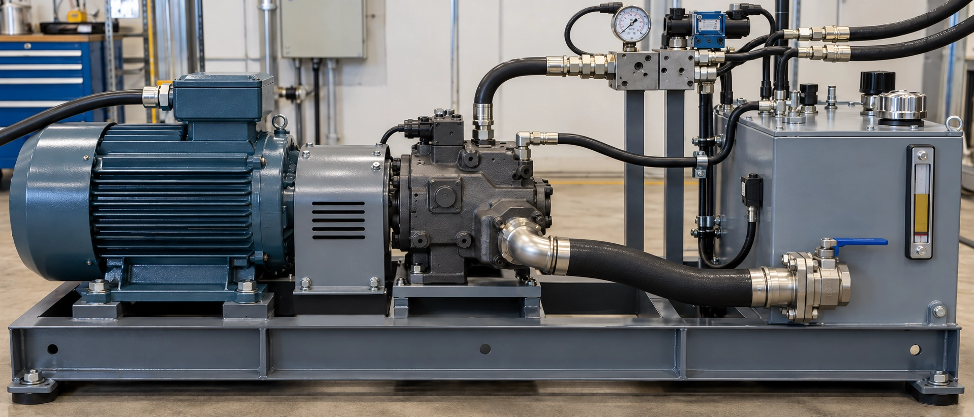
Review three possibilities after a rebuild or replacement:
01 · Installation or commissioning: incorrect connections, inadequate filling, retained air or insufficient supply may prevent correct operation from the first start.
02 · Unresolved system condition: overheating, contamination, abnormal pressure conditions or restricted drainage may continue to affect replacement components.
03 · Repair or component issue: internal clearances, precision surfaces, assembly or unsuitable parts may prevent the pump from meeting required performance.
The correct distinction requires inspection and evidence. An early failure alone does not establish who or what is responsible.
When Should You Repair or Replace a Hydraulic Piston Pump?
| Evidence available | Appropriate next step | Decision boundary |
|---|---|---|
| Supply, drive, controls or external paths remain unverified | Continue system investigation. | Replacement may leave the original cause unresolved. |
| A control or localized component fault is identified | Assess the applicable repair and verify performance afterward. | Confirm the repair scope and acceptance basis. |
| Pump performance remains unacceptable under approved conditions | Obtain internal inspection or specialist testing. | Pressure alone does not establish which parts need replacement. |
| Internal damage is confirmed | Compare localized repair, rebuild and replacement options. | Use inspection findings, parts availability, verification, compatibility, lead time and downtime requirements. |
| A replacement is required | Confirm the complete configuration before ordering. | A similar appearance or shortened model name does not establish compatibility. |
Do not use a universal repair-cost percentage or operating-hour threshold. The decision depends on actual damage, available repair route, replacement specification and machine requirements. Before recommissioning, address any confirmed external cause that could damage the pump again.
Hydraulic Piston Pump Replacement Options
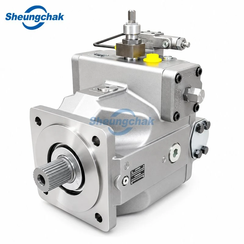
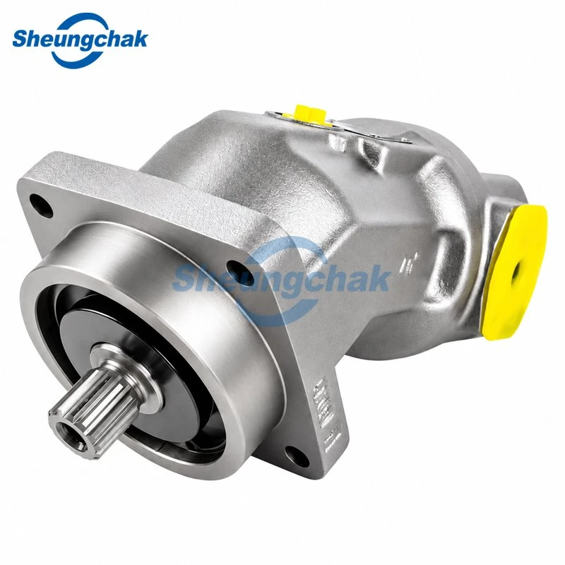
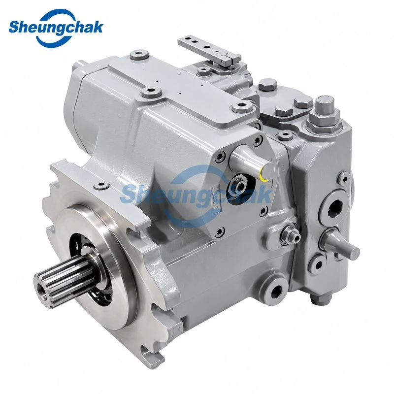
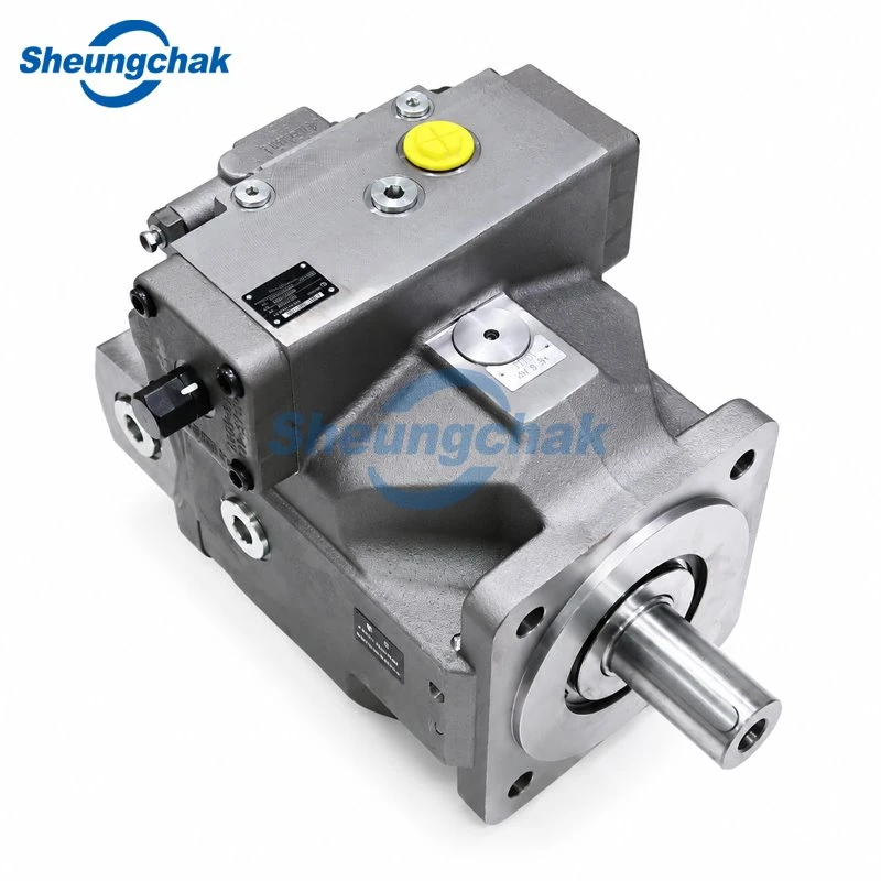
Published product families can help start a matching discussion. Each configuration must be checked against the complete installed model and application.
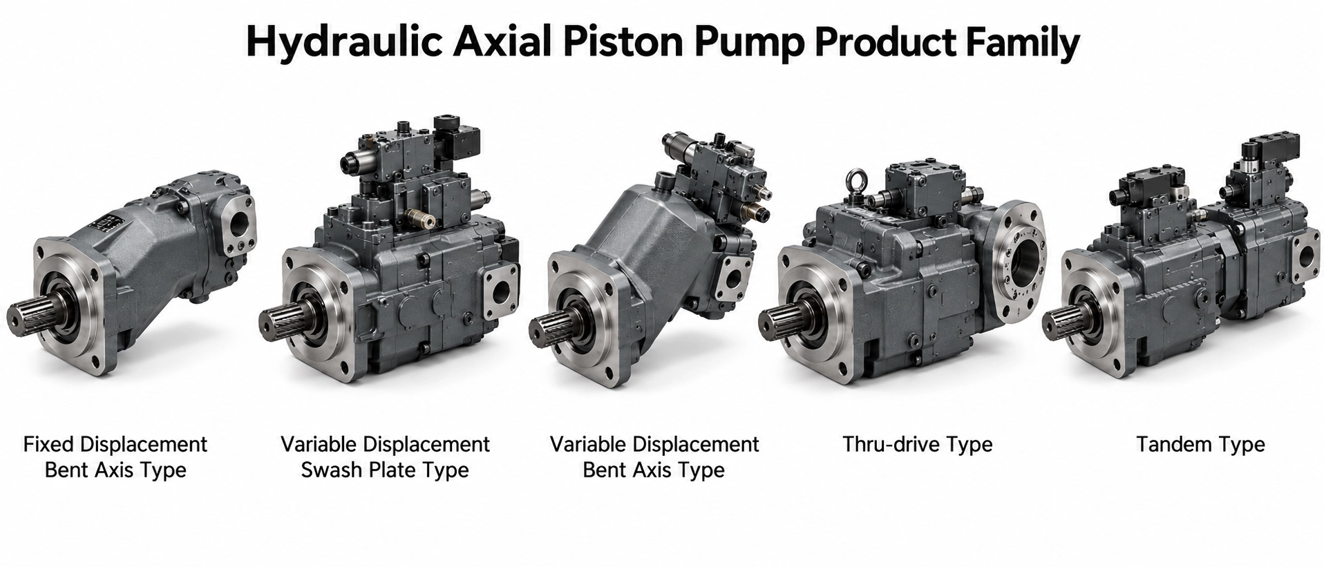
| Product family | Published circuit type | Key matching information |
|---|---|---|
| A10VSO variable-displacement pump | Open circuit | Complete series and control code, displacement, rotation, shaft, flange, ports and through-drive configuration |
| A4VSO variable-displacement pump | Open circuit | Displacement and control configuration, mounting and drive interfaces, rotation, ports and fluid requirements |
| A4VG variable-displacement pump | Closed-circuit hydrostatic transmission | Series, displacement, control version, rotation, mounting, working ports and charge-supply configuration |
These families are not interchangeable replacements. Selection should follow fault assessment and configuration review.
Request Pump Matching and Replacement Support
For fault assessment, provide the measurements to the qualified technician responsible for the machine. For a replacement inquiry, prepare:
- A clear nameplate photograph and complete model code.
- Machine application and circuit type.
- Required pressure and flow, operating speed and duty conditions.
- Control configuration, rotation, shaft, flange and port information.
- Fluid designation and operating temperature.
- Fault measurements, recent maintenance and confirmed inspection findings.
- Required quantity.
Label missing measurements as "not measured" rather than estimating them. Submit a pump matching and replacement inquiry to discuss configuration and quotation. A replacement quotation does not establish the cause of pressure loss; keep unresolved fault questions with the qualified technician responsible for the machine.
Low pressure is a symptom, not a pump diagnosis. Check supply, drive, control and external circuit conditions; record readings under documented operating conditions; then compare pump performance with the requirements for its exact model.
Technical reference scope: Danfoss Series 45 Frame K2 open-circuit service manual, April 2017, alongside cited references. Product configurations, fluid requirements and document revisions may require different specifications. This is an independent troubleshooting overview, not an official manufacturer service procedure.