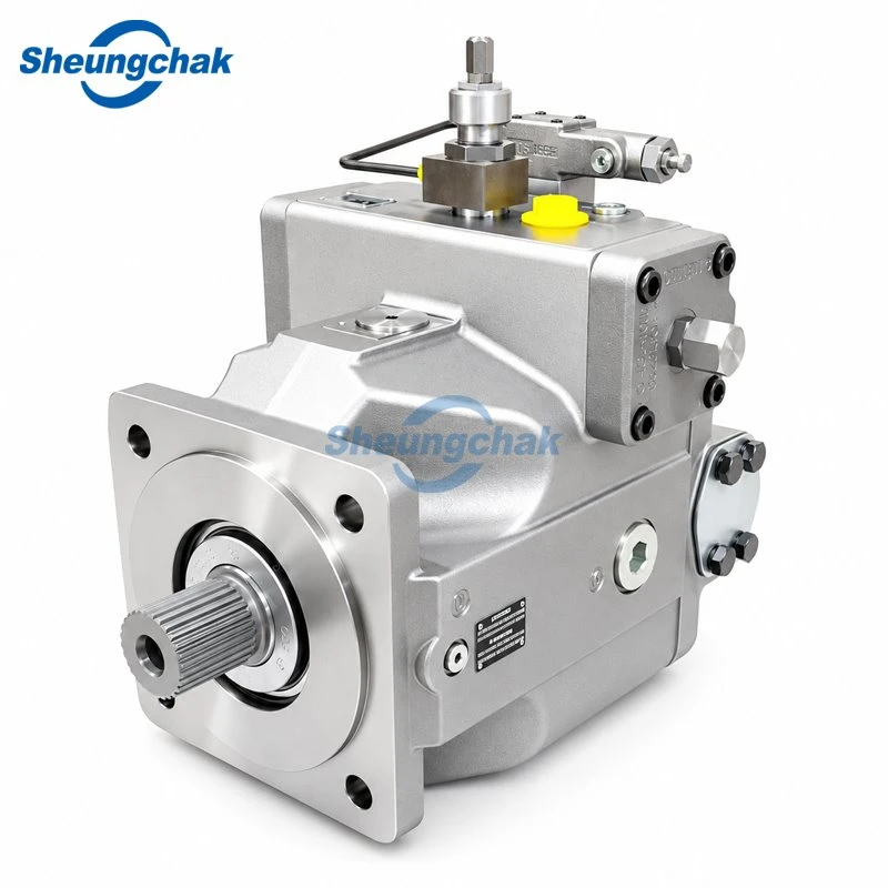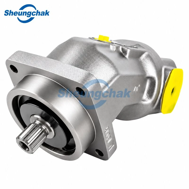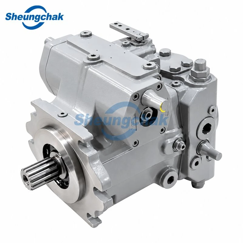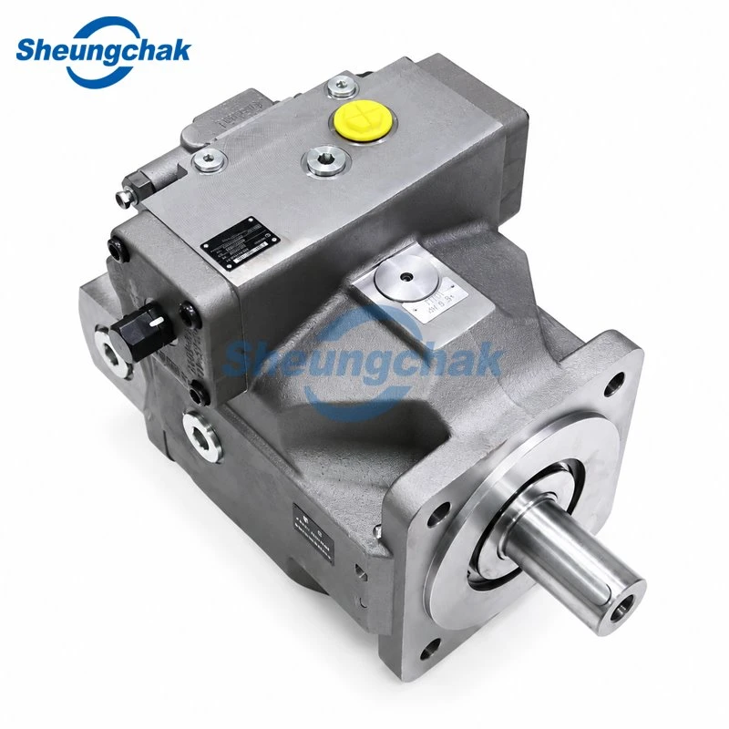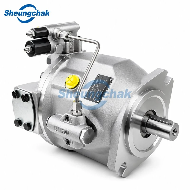

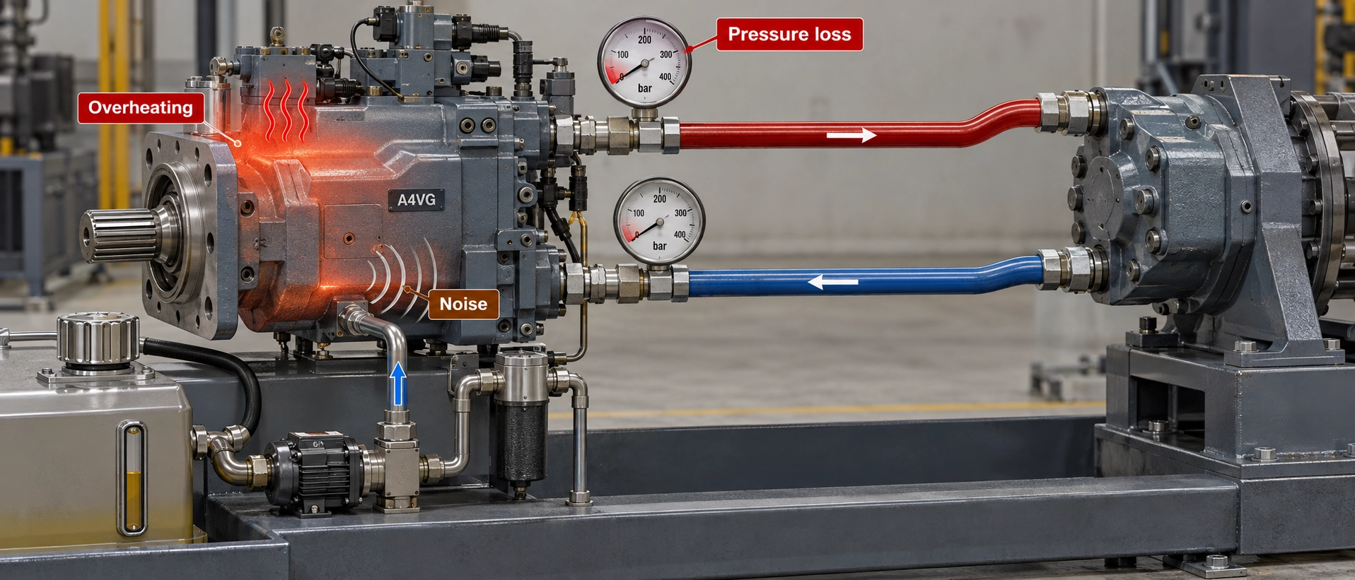
An A4VG pump failure may appear as weak hydrostatic drive performance, pressure loss, unusual noise, vibration or excessive hydraulic fluid temperature. However, these symptoms do not automatically mean that the pump's rotating group is worn out. Low boost pressure, inadequate suction conditions, faulty controls, restricted case drainage and problems elsewhere in the closed circuit can produce similar symptoms.
The most useful diagnostic approach is to identify the symptom, measure the relevant pressures and temperatures under documented conditions, and separate system faults from evidence of internal pump damage before deciding on a repair or replacement.
6
Common symptom patterns
0.8
bar abs
Min. continuous suction at port S
2
bar
Max. continuous case-to-ambient
115
°C
Max. component temperature
What the OEM manual says. Bosch Rexroth's A4VG Series 32 instruction manual, RE 92003-01-B/12.2015, identifies multiple possible causes for insufficient flow, insufficient pressure, unusual noise, vibration and overheating. It also recommends systematic troubleshooting at reduced operating conditions where possible. (Bosch Rexroth, A4VG Series 32 Instruction Manual)
Quick Symptom Checklist
| Observed symptom | What to check first | Why it matters |
|---|---|---|
| Weak drive or pressure loss | Boost pressure, control pressure, drive speed and suction conditions | Insufficient oil supply or control pressure can limit pump output |
| Weak performance when hot | Fluid temperature, viscosity and pressure readings under comparable loads | Temperature changes may expose leakage or supply problems |
| Weak drive in one direction | A/B working pressures and directional control response | The two operating directions may reveal different control or circuit faults |
| Whining or unusual noise | Fluid level, suction conditions and air bleeding | Air entrainment or inadequate inlet supply can cause abnormal noise |
| Excessive vibration | Coupling, mounting, rotational speed and bearing condition | Vibration is not necessarily caused by damaged pistons or other rotating-group components |
| Overheating | Inlet temperature, cooling, pressure-control valves and flushing flow | Excess heat can originate outside the pump's rotating group |
⚠ Safety: Hydrostatic systems can retain dangerous pressure after shutdown. Inspection and measurement must follow the machine manufacturer's procedures and be performed by qualified personnel. Isolate and depressurize the system before opening connections. Never loosen a pressurized hydraulic fitting to obtain a pressure reading.
Why an A4VG "Failure" Is Often a Circuit Problem First
The A4VG is a variable-displacement axial piston pump designed for closed-circuit hydrostatic drives. Its swashplate changes pump displacement and flow direction, allowing the hydraulic motor's direction of operation to be controlled through the two main working lines.
In a closed circuit, most working fluid returns directly between the pump and motor rather than flowing through the reservoir after every pass. The circuit therefore depends on an adequate supply of replenishment oil and on properly functioning pressure and displacement controls.
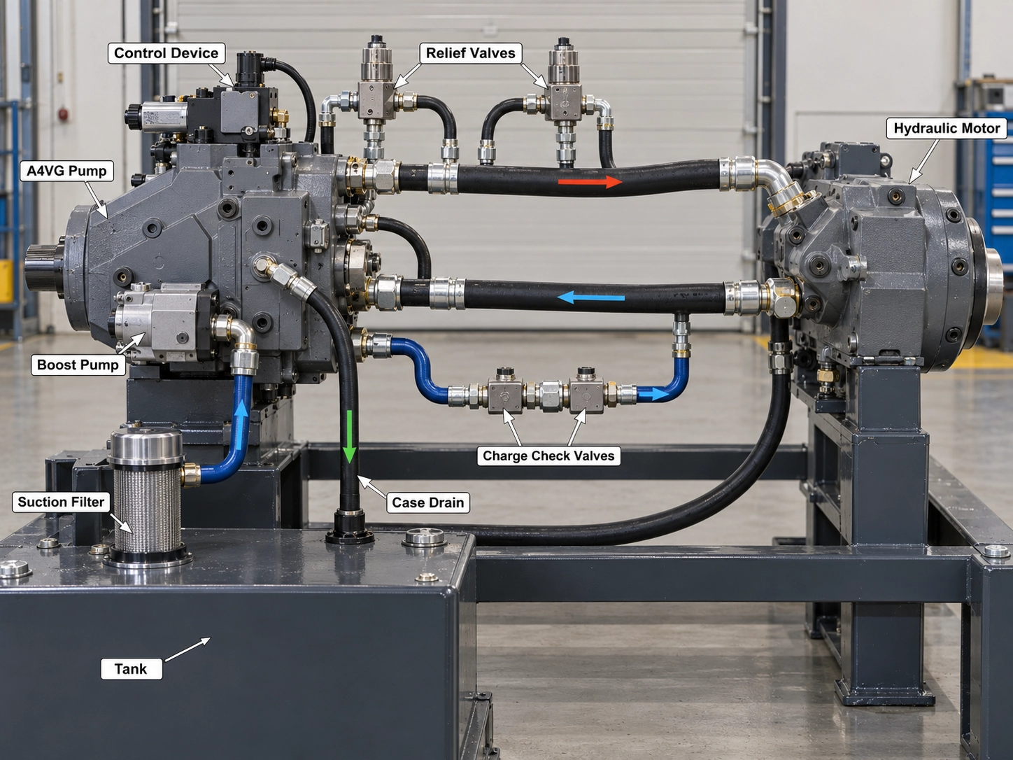
This arrangement means that several components can influence the same symptom:
Support replenishment of internal leakage losses and the low-pressure side of the circuit. Depending on configuration, the boost supply also supports control functions.
Protect the circuit from excessive working pressure. Incorrect operation can affect available drive pressure and generate heat.
Limits pressure by influencing pump displacement. Incorrect function or settings may reduce output.
Determines the pump's displacement response to hydraulic, mechanical or electrical commands.
Helps exchange heated working fluid for cooler replenishment oil. Insufficient flushing can contribute to overheating.
For additional background on the different oil paths, see open-circuit versus closed-circuit piston pumps.
The diagnostic consequence is straightforward: a pump that does not develop the expected output may have a supply, control or circuit problem rather than an internal rotating-group failure. These possibilities must be separated by measurements.
Reference scope. The technical values below refer primarily to the Bosch Rexroth AA4VG Series 32, sizes 28–125, Americas data sheet RE-A 92003/06.2018. The cited Series 32 operating manual is the December 2015 edition.
The referenced data sheet specifies the AA4VG for HLP mineral oil according to DIN 51524, and its published working-pressure range is based on mineral-oil hydraulic fluids. Other hydraulic media require confirmation against their applicable specifications. Other A4VG series, sizes, configurations and later document revisions also require their own technical documentation. (Bosch Rexroth, RE-A 92003/06.2018)
Symptom 1: Pressure Loss or Weak Drive
Weak drive performance is not the same thing as confirmed pump wear. The first task is to determine whether the system lacks working pressure, flow, displacement response or sufficient input power.
The A4VG Series 32 troubleshooting table associates insufficient pressure or flow with several possible causes, including inadequate air bleeding, poor suction conditions, low boost or control pressure, defective controls, drive problems and mechanical wear. It also identifies faults in the driven output unit as possible causes of insufficient pressure.
A useful initial sequence is:
01 · Confirm the symptom
Confirm the operating symptom, recent maintenance and conditions under which the failure occurs.
02 · Verify the drive
Verify drive speed, available drive power and coupling condition.
03 · Check fluid and suction
Check reservoir fluid level, suction restrictions, air entrainment and operating fluid condition.
04 · Measure boost and control pressure
Measure boost pressure and the relevant control pressure using the machine's specified test points.
05 · Record A/B working pressures
Record working pressures at the appropriate A/B measurement points under controlled conditions.
06 · Investigate internal wear last
Investigate internal pump wear only after supply, control and downstream causes have been reasonably excluded.
These are diagnostic priorities, not instructions to change pressure settings. (Bosch Rexroth Instruction Manual, Chapter 14)
Weak When Hot
A machine that drives normally when cold but loses performance after reaching operating temperature presents a different diagnostic problem from one that cannot generate pressure at startup.
Temperature changes the viscosity of hydraulic fluid. Lower viscosity can make existing internal leakage more consequential, but weak hot performance alone does not establish that the rotating group is worn.
10–400
mm²/s
Continuous operating viscosity
16–36
mm²/s
Optimum viscosity range
For the referenced AA4VG Series 32 data sheet, these are operating limits and preferred conditions, not evidence that a particular pump is healthy or damaged.
Compare cold and hot measurements at similar drive speeds, loads and control commands. Record:
- Temperature at the identified measurement location
- A and B working-line pressures
- Boost and applicable control pressures
- Case pressure
- Drive speed and actual machine response
A hot-condition pressure drop accompanied by insufficient boost pressure or control pressure should lead to further investigation of those circuits before the rotating group is condemned.
Conversely, if supply and control conditions are confirmed acceptable while efficiency or internal leakage deteriorates under comparable operating conditions, pump wear becomes a stronger possibility.
Weak in One Direction Only
An A4VG can reverse flow through the main working ports. Consequently, comparing forward and reverse performance can help identify whether the fault follows a particular operating direction.
For example, a directional control problem or abnormal pressure behavior on one side of the closed loop may produce asymmetric drive performance.
Measure the working pressures on both sides using the correct circuit and port identification. Also compare the directional command with the expected displacement response.
Do not assume that different A/B readings prove one high-pressure relief valve is defective. The driven motor, directional loading, pressure cut-off behavior and control arrangement must also be considered.
For detailed differences between available hydraulic and electrohydraulic configurations, refer to the A4VG control options and replacement matching guide.
No Pressure After a Rebuild

If the pump fails to build working pressure immediately after a rebuild or replacement, review what changed during the work before assuming that newly installed parts are defective.
Relevant checks include correct rotation, coupling engagement, clean fluid supply, filling and air bleeding, correct line connections, and the pump's control configuration.
A supplier-published A4VG180 repair case describes a pump rebuilt using replacement cylinder-block and port-plate components that had been ground before delivery. After poor pressure and flow performance during testing, inspection identified abnormal contact patterns and a potential sealing problem between the mating surfaces. The repair technician subsequently reworked and matched the friction pair, reassembled the pump and reported satisfactory testing.
Treat this case as a lead, not a diagnosis. This is an individual commercial repair report concerning an A4VG180, a size outside the NG28–125 range of the AA4VG Series 32 data sheet cited here. It is not independent evidence that the same defect is widespread. Its measurements also lack sufficient standardized reporting details for use as general diagnostic limits. (Super-Hyd, A4VG180 repair case)
A repair cannot be accepted solely because the pump rotates or produces some pressure. Its measured behavior must be compared with the applicable specification and test conditions.
Symptom 2: Noise and Vibration
Unusual pump noise should be investigated promptly, but sound alone cannot identify a failed rotating group.
The Rexroth Series 32 instruction manual lists insufficient air bleeding and poor suction conditions among the possible causes of unusual noises. Under the same malfunction category, it also lists excessive drive speed, incorrect direction of rotation, improper mounting, problems with attachments or coupling installation, oscillation of pressure-limiting or pressure-control valves, and internal mechanical damage.
The manual separately identifies increased or unusual vibration, with worn bearings listed as its possible cause. This distinction matters: the manual does not classify all of the preceding noise-related causes as entries under the independent vibration malfunction category.
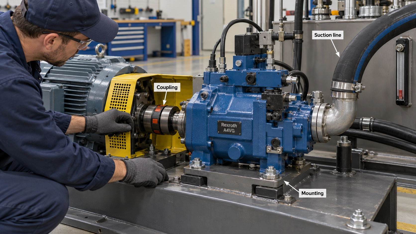
In practice, a technician may still need to examine drive speed, mounting and coupling condition when investigating a vibration complaint. However, these checks should not be presented as proof that vibration originates inside the pump.
Check the Inlet Supply Before Interpreting Noise as Mechanical Failure
Air entering the suction line, excessive inlet restriction or an unsuitable fluid viscosity can interfere with hydraulic fluid supply. Cavitation and air entrainment can produce abnormal sound and may contribute to component damage.
0.8
bar abs
Min. continuous suction, port S (≤30 mm²/s)
0.5
bar abs
Short cold start (<3 min)
Absolute is not gauge. These values are conditional limits, not recommended normal suction pressures. A gauge reading cannot be compared directly with an absolute-pressure limit without accounting for atmospheric pressure and instrument reference.
For unusual vibration, the investigation should include bearing condition and other possible mechanical sources, alongside the machine's coupling, mounting and drive arrangement. These checks are part of fault isolation rather than a diagnosis based on sound or vibration alone.
Persistent mechanical vibration, accompanied by evidence of bearing damage or abnormal internal wear, warrants specialist assessment. Continuing to run an obviously damaged unit risks additional component damage.
The Series 32 malfunction table provides the basis for distinguishing these fault categories. (Bosch Rexroth Instruction Manual, p. 61)
Symptom 3: Overheating of Fluid and Housing
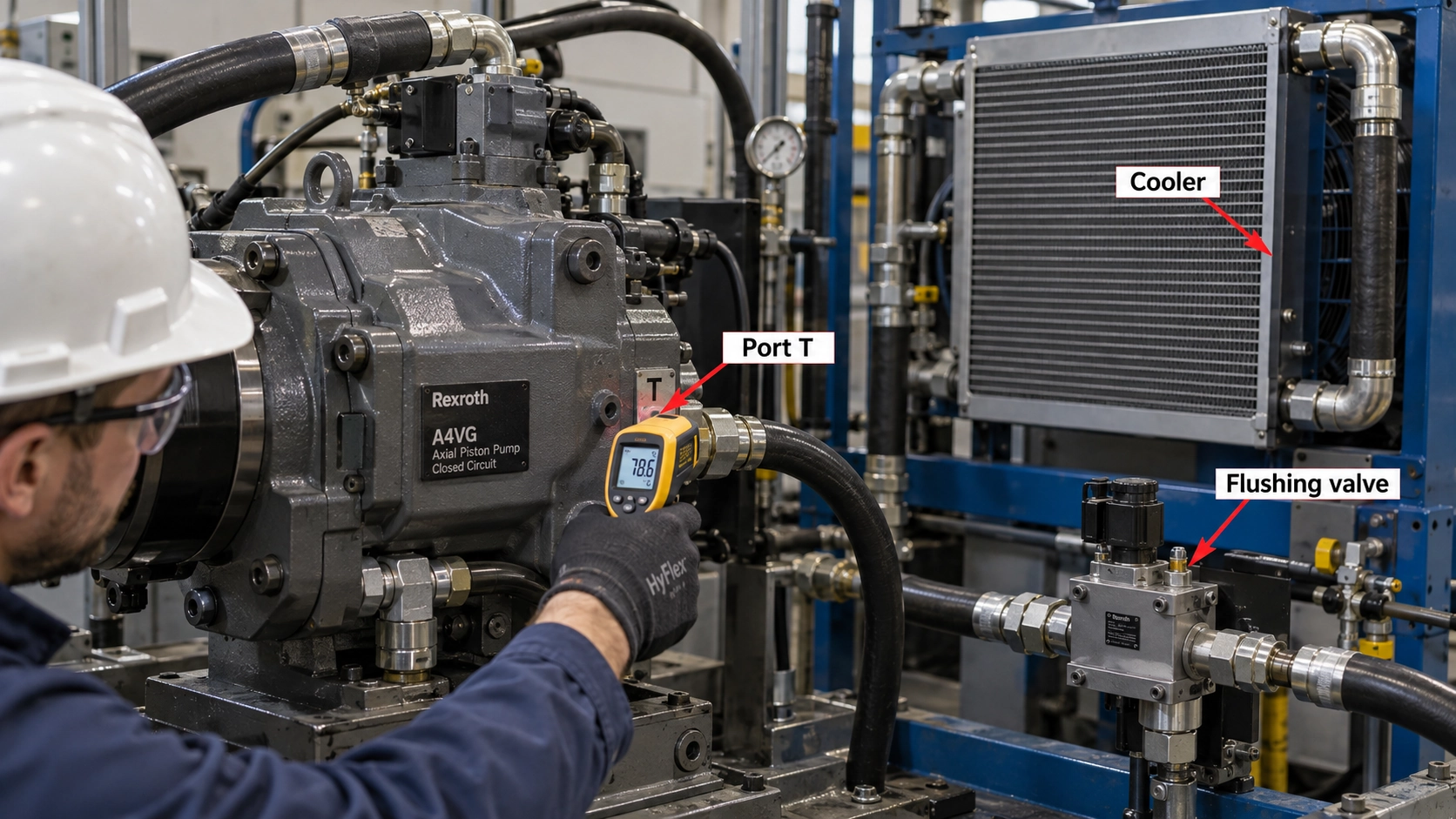
Excessive hydraulic fluid or housing temperature does not automatically mean that the pump needs replacement.
The OEM troubleshooting table identifies excessive inlet temperature, problems with pressure-limiting or pressure-control valves, inadequate flushing flow and worn pump components as possible causes.
A practical investigation therefore starts by separating heat generated within the hydrostatic circuit from heat that the cooling system fails to remove. Check the reservoir level, cooler condition and inlet fluid temperature. Then examine whether the pressure-control system is operating as expected and whether the installed flushing arrangement is functioning correctly.
For the referenced 2018 data sheet:
| Thermal parameter | Published condition |
|---|---|
| Hydraulic fluid temperature at port T | Continuous operating range: −25 to +110 °C |
| Maximum component temperature | No point on the component above 115 °C |
| Bearing/shaft seal temperature difference | Approximately 5 K above the port T reference temperature |
| Optimum operating viscosity | 16–36 mm²/s |
| Minimum short-term viscosity | 7 mm²/s, for less than 3 minutes at pressure below 0.3 × nominal pressure |
The component temperature ceiling is not a desired operating target. A hydraulic system should operate within the permissible viscosity and temperature conditions established for its actual duty cycle.
Name the measurement location. Reservoir temperature, drain-port fluid temperature and an external housing surface measurement are not interchangeable.
If flushing flow is inadequate, heated oil may remain in the working loop for longer than intended. If pressure-control components cause excessive throttling or relief flow, hydraulic power can be dissipated as heat.
Where internal leakage is confirmed to be excessive, it may also contribute to heating. However, temperature alone does not identify how much leakage originates in the pump.
Compare the findings with the applicable hydraulic circuit design and data sheet rather than adjusting relief-valve settings experimentally. (Bosch Rexroth Data Sheet, pp. 5–6; Bosch Rexroth Instruction Manual, p. 64)
Readings That Separate Pump Wear from System Faults
The strongest diagnosis comes from measurements that distinguish inadequate supply, control malfunction, external circuit losses and internal leakage.
A single reading rarely establishes all of these conditions. The measured pressure must be associated with a specific port, operating condition and instrument reference.
Boost and Control Pressure Versus Case Pressure
The following values are taken from the AA4VG Series 32, NG28–125, RE-A 92003/06.2018 data sheet.
| Parameter | Published value | Important qualification |
|---|---|---|
| Nominal boost-pump pressure rating | 25 bar | A component rating, not a universal machine-specific boost-relief setting |
| Maximum boost-pump pressure rating | 40 bar | Not a normal diagnostic target |
| Minimum low-pressure-side working pressure | 10 bar above case pressure | Applies to the low-pressure working line A or B |
| Minimum control pressure, EP/HD/HW | 20 bar above case pressure | Stated for n = 2000 rpm; requirements depend on operating conditions |
| Minimum control pressure, DA/DG/EZ/ET | 25 bar above case pressure | Stated for n = 2000 rpm; requirements depend on operating conditions |
The distinction matters because a reading near a boost-pressure value is not automatically a valid measurement of the high-pressure working line.
The 25 bar and 40 bar values describe published boost-pump pressure ratings; they do not prescribe the boost-pressure relief-valve setting for every A4VG installation. The actual setting must be established from the machine manufacturer's hydraulic schematic, the ordered pump configuration and the applicable technical documentation.
Likewise, the minimum control-pressure figures are not universal machine settings. Actual requirements depend on the control version, speed, operating pressure and the configuration of the stroking mechanism.
Verify the gauge before the diagnosis. Before diagnosing low output, confirm that each pressure gauge is connected to the intended point and that the measured value is being compared with the correct specification. The applicable control configuration and machine manufacturer's hydraulic schematic take priority over generalized troubleshooting numbers. Unauthorized changes to factory pressure settings must not be used as a diagnostic shortcut. (Bosch Rexroth Data Sheet, p. 7)
Case Pressure and the Drain Line
Case pressure is important for understanding shaft-seal loading and housing drainage. However, different published pressure limits describe different physical constraints. Three separate specifications must be considered:
Continuous case-to-ambient differential pressure: The A4VG Series 32 instruction manual states that the continuous case pressure relative to ambient pressure must not exceed 2 bar, with case pressure remaining above ambient pressure.
Permissible shaft-seal pressure differential: The 2018 AA4VG Series 32 data sheet provides a curve that varies with pump size and rotational speed. This determines an additional operating limitation rather than a universal fixed pressure target.
Drain-port pressure rating: The relevant T1/T2 port tables in the 2018 data sheet list a maximum port pressure rating of 3 bar. This port rating must not be interpreted as permission to operate the housing continuously at a 3 bar pressure differential in every application.
These limits describe different requirements and must be considered together with the actual pump configuration, measurement reference and operating conditions. A permissible port rating cannot override a more restrictive continuous operating or shaft-seal limitation.
10 bar is a transient allowance, not a target. The OEM documentation also permits momentary pressure peaks up to 10 bar for less than 0.1 seconds. This is an exceptional transient allowance, not a continuous operating limit or a target pressure. Repeated pressure peaks and higher mean differential pressure can reduce shaft-seal life.
Consequently, it is inappropriate to apply one universal case-pressure limit to every A4VG size and operating speed.
A restricted drain line, unsuitable return-line arrangement or excessive backpressure can increase housing pressure and shorten shaft-seal life.
Inspect the drain routing and associated components against the approved installation instructions. A filter or other restriction introduced into the case-drain path requires particular attention because it can add unwanted backpressure. Drain-line restrictions must not be increased to maintain a higher operating pressure.
Case pressure should be checked at the specified location with an appropriate instrument and compared against all relevant limits, including the shaft-seal differential pressure for the actual pump size and rotational speed. (Bosch Rexroth Data Sheet, p. 6 and applicable port tables; Bosch Rexroth Instruction Manual, Section 2.3)
Case Drain Flow: A Trend, Not a Universal Number
Case drain flow can provide useful information about internal leakage and pump condition, but it must be interpreted with care.
As precision surfaces wear, internal leakage may increase. However, the observed drain flow also depends on pressure, rotational speed, fluid viscosity and the oil paths connected to the housing.
In a closed-circuit hydrostatic drive, the configuration of flushing and boost-relief return paths can further complicate measurements. A measured drain-flow total should not automatically be treated as leakage from the rotating group alone.
A 2025 peer-reviewed conference paper by Ahmad Al-Issa, Tobias Schulze and Jürgen Weber examines case-drain flow monitoring in an industrial hydraulic system containing three axial piston pumps.
According to the publicly available abstract, the methodology combines case-drain flow measurements with other operating parameters and compares results against reference conditions to evaluate performance degradation.
The study supports the value of controlled measurements and baseline comparisons. It does not establish a universal acceptable A4VG case-drain flow in L/min. Nor does its publicly available abstract provide a field-test procedure that can be transferred directly to every mobile hydrostatic drive.
The study is identified by DOI 10.1115/DETC2025-169401. The interpretation here is limited to the publicly available abstract, not the unverified full experimental report. (Al-Issa et al., 2025, TU Dresden research record and ASME conference paper abstract)
Compare against a baseline. The practical objective is to compare repeatable readings against a known healthy baseline, suitable OEM acceptance criteria or an approved specialist test procedure. Do not deliberately force a mobile hydrostatic drive into a high-pressure stalled condition merely to reproduce a laboratory measurement method.
Fluid Condition and Cleanliness
Poor fluid condition can undermine both pump performance and the reliability of a diagnosis.
20/18/15
Min. cleanliness, ISO 4406
19/17/14
ISO 4406 at 90–110 °C (port T)
β20≥100
Recommended filter elements
Viscosity, contamination, fluid aging and water ingress should be considered when investigating repeated failures. A newly rebuilt pump installed into a contaminated circuit remains exposed to the same contamination source.
Where appropriate, use laboratory fluid analysis and review the maintenance history rather than judging fluid condition by visual appearance alone. (Bosch Rexroth Data Sheet, pp. 5–6)
A4VG Diagnostic Measurement Record
The following blank record is a proposed troubleshooting template, not a completed test report or an OEM acceptance specification.
Before taking measurements, identify the exact pump model and approved test points from the machine's hydraulic schematic and applicable technical documents. Use instruments with suitable pressure ratings, measuring ranges, compatible connections and known calibration status. Record whether each pressure reading is gauge, absolute or differential.
Also document drive speed, load, operating direction, control command and oil temperature for each measurement. These readings may need to be taken at different times or operating conditions; they should not be assumed to be simultaneous unless the test arrangement supports synchronized measurement.
Any measurement procedure must follow the machine manufacturer's approved safety instructions and must not require opening pressurized connections or imposing an unauthorized load.
| Measurement | Observed reading | Conditions and comparison |
|---|---|---|
| Full pump model code / series | __________ | Nameplate and applicable data sheet |
| Hydraulic fluid grade | __________ | Manufacturer-approved specification |
| Fluid temperature at port T | __________ °C | Cold or stabilized operating condition |
| Drive speed | __________ rpm | Load and command recorded |
| Suction pressure at port S | __________ bar absolute | Record oil temperature, viscosity, speed and operating condition |
| Working pressure A | __________ bar | Operating direction and load |
| Working pressure B | __________ bar | Operating direction and load |
| Boost pressure | __________ bar | Identify actual measurement port |
| Control pressure | __________ bar | Identify control version and port |
| Case pressure | __________ bar | Record gauge/absolute reference and operating conditions |
| Case drain flow, if safely measured | __________ L/min | Record circuit configuration and validated test method |
| Fluid cleanliness | __________ ISO 4406 | Laboratory or calibrated measurement |
| Observed noise or vibration | __________ | Record the associated operating condition |
| Operating direction | __________ | Forward/reverse and corresponding A/B pressure roles |
| Control command | __________ | Command value and control version at the time of measurement |
| Load / test condition | __________ | Describe machine load and whether the reading is cold or stabilized |
| Test point and pressure reference | __________ | Identify port and gauge, absolute or differential basis |
This record becomes more useful when the same measurements are available from a known healthy pump or a documented acceptance test.
When the Pump Fails Again After a Rebuild or Replacement
An early repeat failure should trigger an investigation into both repair quality and the conditions surrounding installation.
Replacing damaged components does not correct an external problem such as contaminated oil, inadequate replenishment supply, restricted drainage or insufficient cooling.
Commissioning deserves particular attention. In Section 8.1.1 of its Series 32 operating manual, Rexroth requires appropriate filling and air bleeding before operation. The manual recommends using a filling unit with a 10 µm filter grade and describes checking that the hydraulic fluid discharged from the drain port is free of air bubbles.
The manual also calls for verification of boost pressure, working pressure, case pressure and suction pressure during commissioning. These are essential checks for establishing whether the newly installed unit is receiving and controlling hydraulic fluid correctly. (Bosch Rexroth Instruction Manual, pp. 48–50)
A post-rebuild investigation should distinguish three possibilities:
01 · Installation or commissioning problem
Incorrect connections, inadequate filling, retained air or insufficient supply may prevent correct operation from the first startup.
02 · System problem that remains unresolved
Overheating, contamination, abnormal pressure conditions or restricted drainage may continue to damage replacement components.
03 · Repair or component problem
Incorrect internal clearances, damaged precision surfaces, assembly errors or unsuitable replacement parts may prevent the pump from achieving expected performance.
The correct distinction requires inspection and evidence. An early failure is not by itself proof that the repair shop or replacement component is responsible.
Repair, Replace, or Keep Testing? What to Record Before You Decide
A repair-or-replacement decision should follow the evidence rather than the severity of the initial symptom.
| Decision | Minimum supporting evidence | What not to assume |
|---|---|---|
| Keep testing | Boost pressure, suction conditions, external controls, cooling or other system components remain unverified. | Replacing the pump will not necessarily correct an unidentified circuit fault. |
| Evaluate repair | The fault has been isolated to the pump, damaged components and mating surfaces can be assessed, and a qualified repair provider can evaluate restoration to the required specification. | A rotating pump or a single acceptable pressure reading does not prove the repair is successful. |
| Consider replacement | Internal mechanical damage or wear is confirmed, reliable repair cannot be established, or a tested replacement better suits the machine's requirements. | A severe symptom alone is not proof that the pump must be replaced. |
The OEM troubleshooting manual identifies replacement as a remedy for certain confirmed mechanical damage and wear conditions. That does not mean every low-pressure or overheating symptom requires a replacement.
For either a repair assessment or replacement inquiry, gather the pump's complete identification and operating evidence before selecting parts.
The exact model code matters because A4VG configurations can differ in displacement, control type, shaft, flange, rotation, pressure-related options and port arrangement. Use the A4VG model code identification guide when checking these configurations.
If the evidence points to an internal pump failure and a replacement is required, the A4VG hydraulic piston pump product page provides a starting point for a replacement-matching inquiry. Submit the complete model code, nameplate photographs and recorded operating conditions so compatibility can be reviewed.
A4VG pump failure should be confirmed through measurable evidence, not diagnosed from noise, heat or pressure loss alone. The most reliable next step is to rule out supply and control problems, record the relevant readings, and evaluate pump wear against the actual model and operating conditions.
Technical reference scope: Bosch Rexroth AA4VG Series 32, RE-A 92003/06.2018, NG28–125, and A4VG Series 32 Instruction Manual RE 92003-01-B/12.2015. Product configurations, hydraulic fluids and document revisions may require different specifications. This is an independent troubleshooting overview, not an official Bosch Rexroth service procedure.