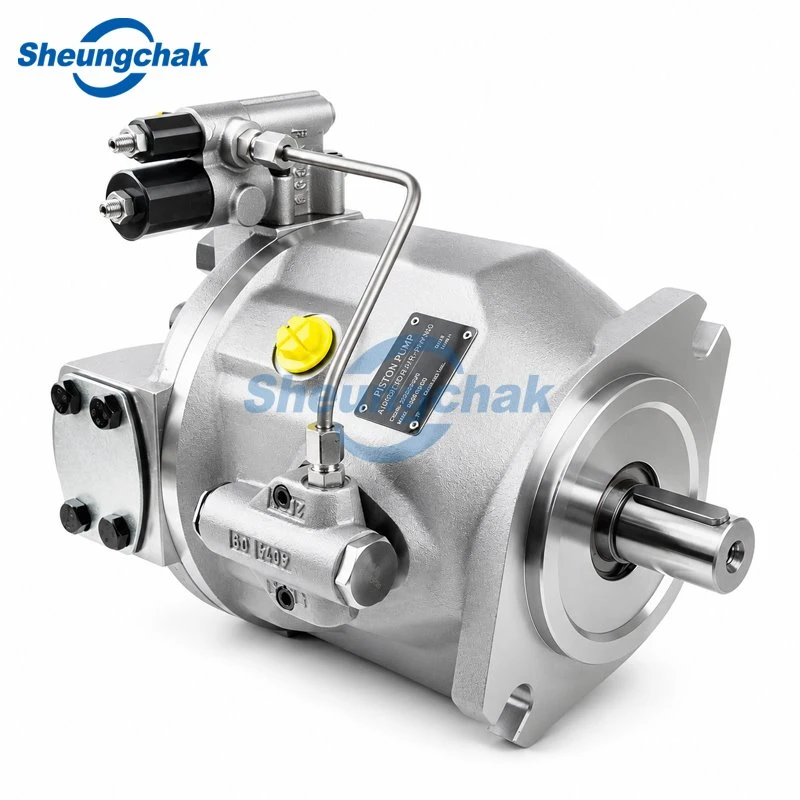

Hydraulic pump cavitation, dissolved gas release, and external air ingress produce similar noise and erratic actuation, but they require different corrective actions: verify the inlet supply path and fluid viscosity first, then compare recorded inlet pressure against the specific pump manufacturer's manual before replacing components.
Cavitation occurs when local absolute pressure at the pump inlet or within its pumping chambers drops below the fluid's vapor pressure, forming vapor cavities that implode when swept into high-pressure zones. Because a noisy pump or cloudy oil in the sight glass can stem from overlapping supply, fluid, or mechanical problems, reliable troubleshooting depends on matching actual inlet conditions, oil temperature, and shaft speed against model-specific documentation rather than applying universal pressure rules.
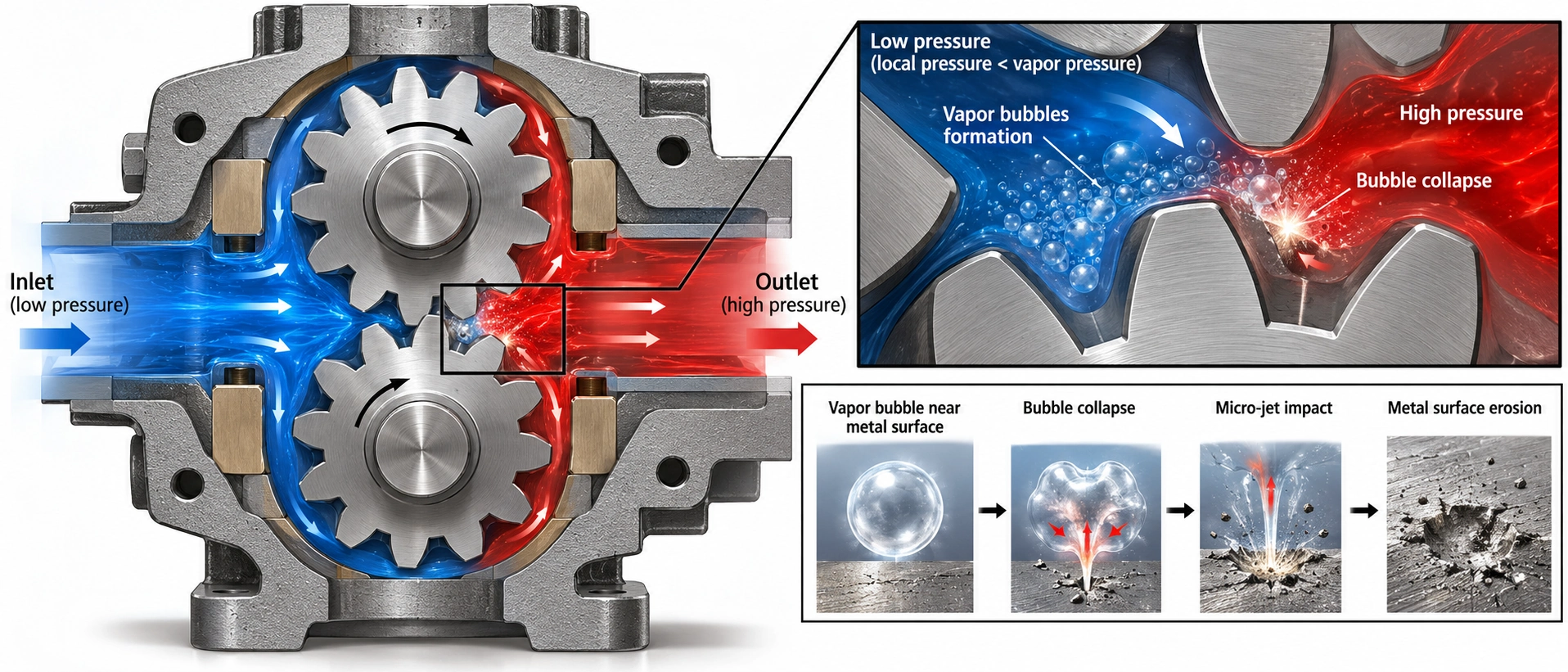
Figure 1: Internal dynamics of vapor bubble formation and collapse in hydraulic positive-displacement pumps.
What hydraulic pump cavitation means
In positive-displacement hydraulic pumps, fluid must fill the expanding pumping chambers at the inlet port as the rotating group turns. When the absolute pressure at the pump inlet falls too low to push fluid into those chambers at the required flow rate, cavities form inside the liquid and subsequently collapse under discharge pressure, eroding metal surfaces on valve plates, cylinder blocks, and pistons or gears.
Technical literature and maintenance discussions do not always use identical boundaries when describing bubble formation in hydraulic oil. To avoid misdiagnosing the supply path, field checks should distinguish three physical mechanisms that frequently occur together or produce similar symptoms:
Vapor formation, gas release and air ingress
01 Vapor cavitation
True vapor formation. When absolute inlet pressure drops below the vapor pressure of the hydraulic fluid at the current operating temperature, the liquid itself flashes into vapor pockets. Once these vapor bubbles travel to the high-pressure outlet zone, they implode rapidly, causing localized mechanical shock and surface pitting.
02 Gaseous cavitation
Dissolved gas release. Hydraulic oil naturally contains dissolved air. As a modelling and test-rig study on axial piston pump cavitation notes, when local pressure at the cylinder block and valve plate interface falls below the gas separation pressure, dissolved gas precipitates into bubbles that collapse upon entering the high-pressure zone and damage interface surfaces (MDPI). Generally, dissolved air begins coming out of solution at pressures higher than the fluid's true vapor pressure. Application guidelines for vane and piston units also note that severely restricted inlets can pull both dissolved air and vapor out of the fluid (Danfoss Vickers Application Manual).
03 Aeration
External air ingress. Air enters the hydraulic system from outside the fluid circuit-typically through leaking inlet connections, damaged pump shaft seals, low reservoir fluid levels, or a return line terminating above the fluid level (Parker eP2/eP3 Service Manual, Effective March 2019; Machinery Lubrication). Unlike vapor cavities that only form in low-pressure zones, entrained air is drawn directly into the suction port and compressed through the pump.
Treating all three as interchangeable leads to wasted maintenance. Tightening suction clamps will not cure true vapor cavitation caused by a clogged inlet strainer or cold, overly viscous oil; conversely, cleaning a strainer will not stop external air from leaking past a degraded shaft seal.
Symptoms that call for investigation
An abnormal pump noise-often described by field practitioners as a high-pitched whine when restricted or an erratic rattling and knocking sound when air is entrained (Machinery Lubrication)-is the most commonly reported warning sign of cavitation or air in the fluid, alongside erosion on the cylinder barrel and valve plate (Parker eP2/eP3 Service Manual, Effective March 2019). However, observable symptoms only indicate that an abnormal operating state exists-they do not isolate the exact failure mechanism on their own.
What noise, foam and performance changes cannot prove
Manufacturer troubleshooting matrices list multiple inlet and fluid conditions under noisy pump operation and high wear (Parker eP2/eP3 Service Manual, Effective March 2019). Furthermore, a steady average reading on a standard service pressure gauge does not rule out early cavitation damage: in a test-rig study on an axial piston pump operating at 1500 r/min and approximately 21.0 MPa at full displacement (sampled for 10 s at 48,000 Hz), researchers used high-frequency pressure sensors to detect discharge waveform and frequency spectrum changes caused by artificial valve-plate cavitation damage measuring 6.0 × 2.0 × 1.0 mm (MDPI).
Relying on sound, visual oil checks, or average gauge readings alone creates several diagnostic traps:
| Observed phenomenon | Candidate causes | Next verification evidence needed | What the symptom cannot prove alone |
|---|---|---|---|
| Abnormal whine, rattling, or knocking noise at pump | Air in fluid or cavitation from leaking inlet connections, low oil level, return line above fluid, high fluid viscosity / cold oil, excessive shaft speed, or insufficient inlet pressure (Parker eP2/eP3 Service Manual, Effective March 2019; Machinery Lubrication). | Compare noise behavior against fluid temperature and shaft speed; inspect suction line joints and strainer condition; check actual inlet pressure against the model manual. | Cannot prove vapor cavitation is the sole mechanism without ruling out external air ingress, and cannot confirm the extent of internal rotary group erosion. |
| Foaming, cloudy, or milky oil in reservoir / sight glass | Air drawn through leaking inlet connections, shaft seal, or return line cascading above fluid; OR water contamination in fluid from condensation or faulty breather/strainer (Parker eP2/eP3 Service Manual, Effective March 2019; Machinery Lubrication). | Check reservoir level and return submergence; inspect suction joints and breathers; perform an oil sample/water check to separate air bubbles from emulsified water. | Milky appearance alone cannot distinguish entrained air from water contamination, nor does the absence of surface foam rule out localized vapor collapse inside the pump. |
| Unstable pressure, sluggish actuator response, or low output | Insufficient inlet supply starving the pump or entrained air compressing in the circuit; alternatively, drive, relief, compensator, or internal leakage faults (hydraulicsc.com). | Verify inlet supply path and fluid level first; if supply conditions meet specification, separate control and internal wear paths. | Cannot prove the pump itself is worn out without ruling out supply starvation and circuit control faults. |
| Steady reading on a standard damped discharge pressure gauge | Normal average discharge pressure, or mechanical gauge damping smoothing out rapid high-frequency pressure pulsations. | Cross-check with inlet conditions, case drain trends, and high-frequency sensor diagnostics where applicable (MDPI). | An average dial reading alone cannot confirm the absence of high-frequency discharge pressure pulsations associated with localized valve-plate damage. |
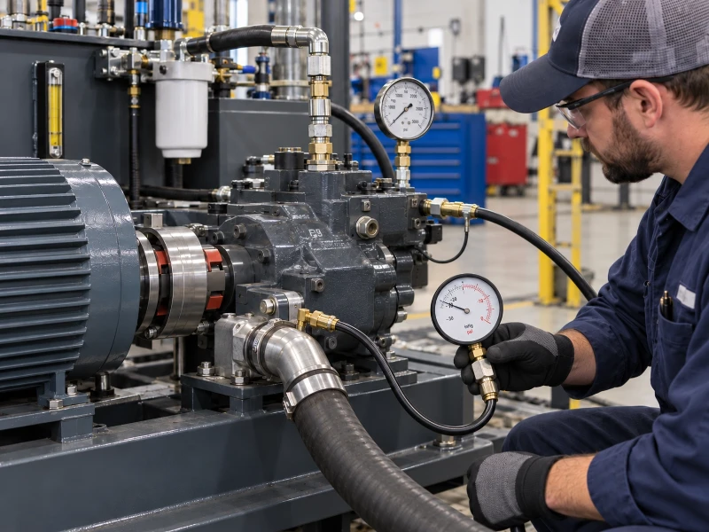
Figure 2: Field technician conducting suction path inspection and inlet pressure measurements.
When low system output or unstable pressure persists after confirming that the reservoir level, fluid viscosity, and suction path are normal, review other causes of piston pump pressure loss to separate drive, relief valve, compensator, and internal wear issues from inlet starvation.
Check the inlet supply path
In open-circuit hydraulic systems, the pump relies on atmospheric pressure (or reservoir pressurization, where designed) and gravity to push oil through the suction line into the inlet port. Any excessive pressure drop along that path-or any condition that prevents air from venting properly-can push absolute inlet pressure below the minimum allowable threshold.
Safety boundary for inspection and testing: Follow the equipment and pump manufacturer's approved lockout, tagout, energy isolation, and depressurization procedures before inspecting or loosening any hydraulic component. All diagnostic measurements on live circuits must be performed by qualified personnel using calibrated instruments at manufacturer-approved test ports. Never loosen pressurized fittings, restrict case drain lines, or raise relief/compensator settings beyond rated limits to troubleshoot pump noise.
Restrictions and reservoir venting
Before disassembling a suspect pump, inspect the physical supply path between the tank and the pump inlet port:
Suction strainers and inlet filters
Clogged internal tank strainers are a frequent source of hidden pressure drop. Field maintenance accounts published in trade literature also document cases where a detached strainer migrated inside the reservoir and intermittently blocked the suction pipe opening, starving the pump without showing an external leak (Machinery Lubrication).
Inlet line geometry and airtight connections
Manufacturer installation instructions require keeping inlet piping free of sharp bends, matching or exceeding the nominal inlet port diameter to limit flow velocity, and maintaining airtight suction connections (Parker eP2/eP3 Service Manual, Effective March 2019). Also verify that tank outlet isolation valves are locked fully open and that suction hoses are not kinked, flattened, or degraded.
Reservoir breather and tank pressure state
In an open reservoir, a plugged air breather prevents atmospheric pressure from acting on the fluid surface as cylinders extend or fluid cools, creating a partial vacuum inside the tank (Machinery Lubrication). Even if a system uses a pressurized reservoir, application manuals warn that reservoir pressurization does not automatically guarantee positive pressure at the pump inlet-particularly during cold starts when high fluid viscosity creates severe pressure drop across the suction piping (Danfoss Vickers Application Manual). Do not attempt to pressurize a reservoir that was not engineered and rated for pressure service.
Cold oil, viscosity and speed
Hydraulic pump cavitation during cold start is directly tied to the relationship between temperature, fluid viscosity, and shaft speed. When hydraulic oil is cold, its kinematic viscosity rises sharply, increasing flow resistance through the suction strainer and inlet piping. If the prime mover immediately accelerates the pump to full rated speed and displacement while the oil is sluggish, the pressure drop across the inlet line can exceed what the tank pressure can overcome.
Manufacturer installation manuals separate permissible viscosity ranges into continuous operating windows and extreme cold-start limits. For example, Parker's installation manual for eP2/eP3 electronic control piston pumps (Effective March 01, 2019, page 9) specifies the following (Parker eP2/eP3 Service Manual, Effective March 2019):
Recommended continuous viscosity
15–40 mm²/s (cSt)
Maximum cold-start viscosity
1000 mm²/s (cSt)
These figures apply specifically to that pump series and manual revision; they are not universal thresholds for every hydraulic pump on the market.
To organize initial field observations before escalating to instrumented testing, maintenance teams can use the following proposed blank inspection checklist (this is a recording template, not a substitute for machine-specific service instructions):
Recent maintenance history
Were hoses, filters, oil grades, breathers, or pump settings changed right before the noise started?
[Record: Yes / No / Details]
Reservoir level & breather
Is oil at the specified level with actuators positioned per the manual, and is the breather cap clean and unobstructed?
[Record: Pass / Fail / Notes]
Suction isolation valve & hose
Is the tank shut-off valve locked fully open, and is the suction hose free of kinks, flattening, or wet/weeping joints?
[Record: Pass / Fail / Notes]
Start-up thermal condition
Does the noise occur only during cold morning starts, or does it persist after the fluid reaches normal operating temperature?
[Record: Cold Only / Continuous / Ambient & Tank Temp]
Interpret inlet pressure for the actual pump
A single vacuum or pressure reading at the suction port has little diagnostic meaning unless it is recorded alongside the pressure reference scale, measurement location, shaft speed, pump displacement, and fluid temperature. Comparing an unverified gauge reading against a generic "rule of thumb" borrowed from another pump type frequently leads to false clearances or unnecessary replacements.
Record pressure reference and operating conditions
When reviewing pump data sheets or recording measurements taken by qualified personnel at manufacturer-approved test ports, verify the pressure reference first:
Absolute vs. gauge pressure
Engineering catalogs for axial piston pumps frequently express inlet limits in bar absolute (bar abs.), where standard atmospheric pressure at sea level is approximately 1.0 bar abs. Service gauges in the field often read in gauge pressure (bar gauge, psi, or inHg vacuum) relative to local ambient atmosphere. Confusing 0.8 bar absolute (a slight vacuum below sea-level atmosphere) with 0.8 bar gauge (positive pressure above atmosphere) will invalidate the entire evaluation.
Operating state at the moment of measurement
Inlet pressure varies significantly between idle unloaded standby and maximum speed at full swashplate displacement. A reading taken at low idle with warm oil will not reveal inlet starvation that occurs at full throttle during cold start.
Read the applicable speed–inlet curve
Pump manufacturers tie minimum allowable inlet pressure directly to shaft speed and displacement. The Danfoss Series 45 axial piston open-circuit pump technical information manual (March 2026 revision, document BC152886483703en-001306, printed pages 45–46) lists these reference values (Danfoss Series 45 Technical Information):
Rated speed defined at
1.0 bar abs.
Minimum continuous inlet
0.8 bar abs.
(reduced max. speed)
Minimum cold-start inlet
0.5 bar abs.
Crucially, the manual requires engineers to consult the specific inlet pressure versus speed curves for each frame size and displacement rather than treating 0.8 bar absolute as a flat operating limit across all speeds (Danfoss Series 45 Technical Information).
Because Danfoss defines rated speed in that catalog at 1.0 bar absolute inlet pressure, minimum allowable limits (such as 0.8 or 0.5 bar abs.) represent boundary conditions rather than normal continuous design targets. Even when another pump family specifies a similar number-for instance, Parker's eP2/eP3 manual also lists 0.8 bar absolute as its minimum inlet pressure at page 4 (Parker eP2/eP3 Service Manual, Effective March 2019)-curves and speed derating rules cannot be transferred across different axial piston, vane, or gear pump families.
When logging inlet data for engineering review, record all variables in the structured template below. Enter not measured for any unconfirmed item rather than estimating values:
| Recording field | Blank field entry template | Why this variable matters |
|---|---|---|
| Pump model code & serial | [Enter full nameplate code] | Determines the exact displacement, control type, and applicable manual. |
| Reference manual & revision | [Document ID / Year / Page] | Ensures limits match the specific pump series and design generation. |
| Fluid grade & measured temp | [ISO VG grade / °C or °F / Sensor location] | Links fluid temperature to actual operating viscosity at the time of test. |
| Shaft speed & displacement state | [RPM / Idle vs. Full Stroke / Load state] | Inlet demand scales with flow rate; readings must match speed-inlet curves (Danfoss Series 45 Technical Information). |
| Measured inlet value & reference | [Value + Unit + Absolute or Gauge + Port location] | Prevents unit conversion errors and confirms proximity to the pump inlet flange. |
| Instrument & calibration status | [Gauge/Transducer range, sampling rate, cal date] | Confirms whether the instrument can accurately resolve vacuum or transient drops. |
Know when a closed-circuit system needs a different check
The suction path checks above apply primarily to open-circuit pumps drawing oil directly from a reservoir. If the machine uses a closed-circuit hydrostatic transmission, checking only the tank-to-charge-pump suction hose is incomplete.
In a closed loop, oil circulates directly between the main piston pump and the hydraulic motor, while an integral or auxiliary charge (replenish) pump supplies cool makeup fluid to the low-pressure side of the loop to compensate for internal leakage and flushing flow. As Parker's application documentation for Gold Cup hydrostatic pumps explains, if replenish flow is insufficient, the main pump becomes starved for fluid on its low-pressure side, leading directly to cavitation damage (Parker Gold Cup Hub).
Closed-circuit cavitation troubleshooting must branch out to include charge pump suction conditions, charge filter pressure drop, charge relief valve performance, and loop flushing losses. Because charge pressure settings and test ports vary strictly by pump family, do not apply open-circuit suction tables or Gold Cup values to other closed-loop units; for Rexroth-type closed-loop units, refer to our dedicated guide on A4VG closed-circuit troubleshooting along with the original manufacturer's service manual.
Correct the cause and prevent a repeat
Stopping hydraulic pump cavitation requires matching the corrective action to the verified supply fault rather than applying generic fixes:
Match the fix to the verified fault
Verified inlet restriction
Clean or replace clogged suction strainers according to the machine maintenance schedule, replace damaged or undersized suction hoses with properly rated hydraulic intake piping, and lock tank isolation valves fully open.
Verified air ingress
Ensure all inlet connections are airtight, repair shaft seal leaks, maintain specified reservoir fluid levels, and verify that return lines terminate below the fluid surface with functional tank breathers (Parker eP2/eP3 Service Manual, Effective March 2019; Machinery Lubrication).
Verified cold-start starvation
Confirm that the hydraulic fluid viscosity grade matches the ambient temperature envelope specified by the equipment builder, start the pump at reduced speed or unloaded conditions until fluid viscosity enters the permissible continuous operating window (Parker eP2/eP3 Service Manual, Effective March 2019), and use reservoir heating equipment where approved by the machine manufacturer.
Recheck after service or replacement
Replacing a noisy or failed pump without diagnosing the circuit that starved it risks immediate repeat downtime. As Parker's service documentation notes, hydraulic problems are often interrelated and component failure can be the effect rather than the root cause; installing a replacement pump into the same restricted or aerated circuit can repeat the failure (Parker eP2/eP3 Service Manual, Effective March 2019).
Whenever a pump is serviced, resealed, or replaced, follow the manufacturer's commissioning sequence before returning the machine to full load:
Fill the pump case. Before starting, fill the pump housing with clean filtered hydraulic fluid through the upper case drain port as specified in the installation manual to ensure internal lubrication at initial rotation (Parker eP2/eP3 Service Manual, Effective March 2019).
Purge trapped air and verify unloaded start-up. Allow the pump to circulate freely under unloaded conditions to purge air from the system (Parker eP2/eP3 Service Manual, Effective March 2019), check for abnormal noise or foaming, and record post-service inlet pressure and temperature under the same baseline conditions used prior to repair.
Evaluate internal wear if cavitation already occurred. If a pump operated under cavitating conditions prior to correcting the inlet restriction, metal particles eroded from the valve plate or cylinder block may have increased internal slippage. While high case drain flow does not diagnose cavitation by itself, interpreting piston pump case-drain measurements under controlled pressure and temperature helps maintenance teams assess whether internal wear requires pump overhaul or replacement.
When to escalate and what to record
Field personnel should stop unapproved adjustments, follow machine lockout procedures, and escalate to qualified hydraulic technicians or the equipment manufacturer when:
- Cavitation noise, severe vibration, or pressure instability continues after verifying reservoir fluid level, breather condition, and external suction line integrity.
- Evaluating the pump requires connecting test instruments to pressurized ports, inspecting internal rotary group erosion, or testing closed-circuit charge systems.
- Metal contamination is found in filters, magnetic plugs, or case drain lines, indicating active surface erosion inside the pump.
No technical guide can predict how many hours a cavitating pump will survive before catastrophic seizure; operating a pump with active vapor collapse risks sending metallic debris throughout downstream valves and actuators.
If inspection confirms a replacement is needed
When qualified inspection confirms that cavitation erosion has damaged the pump beyond economical repair-and after the underlying inlet restriction, air leak, or cold-start viscosity problem has been identified and corrected-preparing complete application data prevents ordering the wrong configuration.
Before requesting a replacement quote, compile the following verified information (enter not measured for any operating parameter not yet captured):
- Complete pump nameplate model code, series number, and serial number.
- Circuit type (open-circuit vs. closed-circuit) and mounting/shaft configuration.
- Hydraulic fluid specification, normal operating temperature range, and minimum cold-start ambient temperature.
- Prime mover shaft speed (RPM) and required system pressure/flow settings.
- Summary of the inlet supply inspection and any recorded inlet pressure or case drain measurements.
If your technical team has confirmed that a damaged axial piston unit requires replacement, you can review hydraulic piston pump replacement options or submit a pump matching inquiry with your nameplate code and recorded operating conditions to confirm model compatibility and specification matching before ordering.