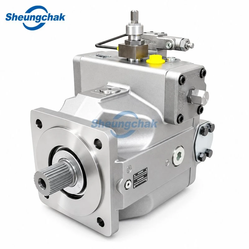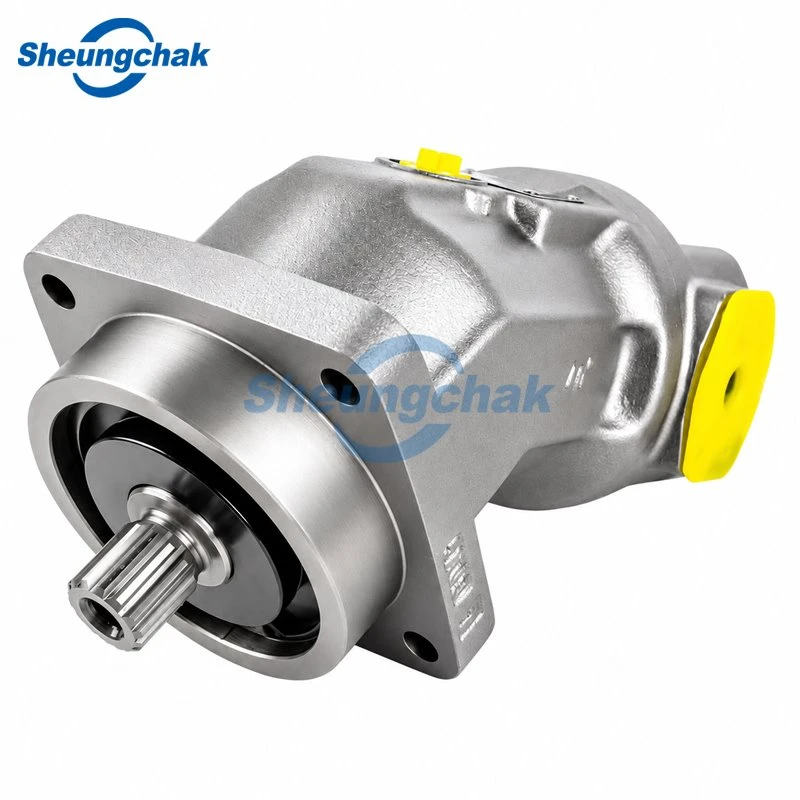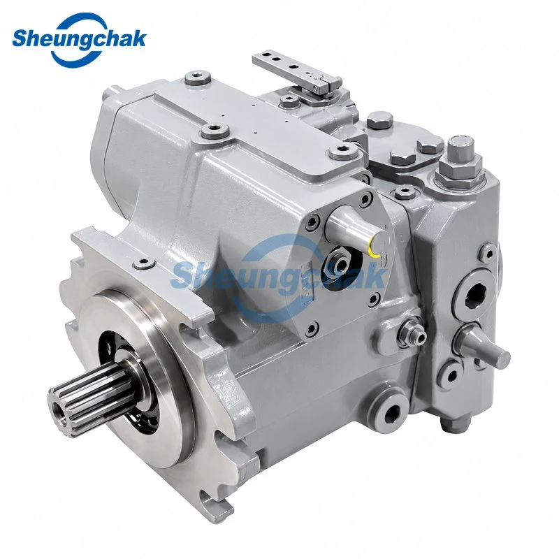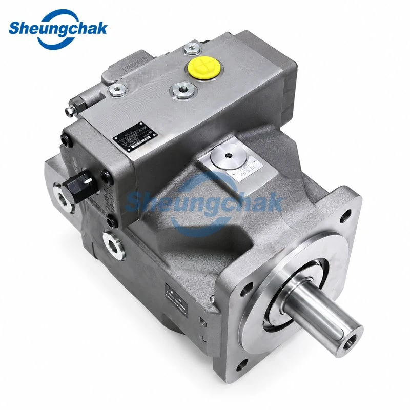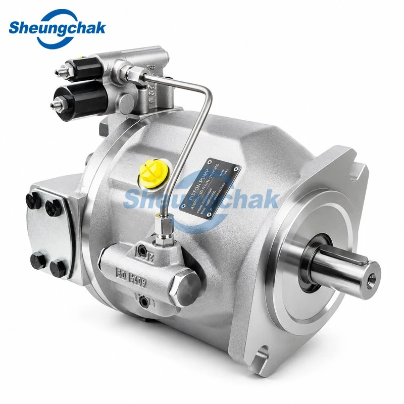

Hydraulic pump filtration helps protect the precision surfaces inside axial piston pumps by reducing their exposure to solid contaminants. Hard particles can damage lubricated interfaces, increase internal leakage, and contribute to premature wear. Effective filtration reduces that risk, but it cannot guarantee a specific service life.
The practical objective is to maintain the oil cleanliness required by the equipment without restricting essential flow. That requires more than choosing a finer filter: the cleanliness target, filter location, removal efficiency, pressure drop, and actual oil condition must work together.
This article focuses on axial piston pumps, including swashplate designs. Filtration requirements for a particular pump must come from its applicable technical documentation.
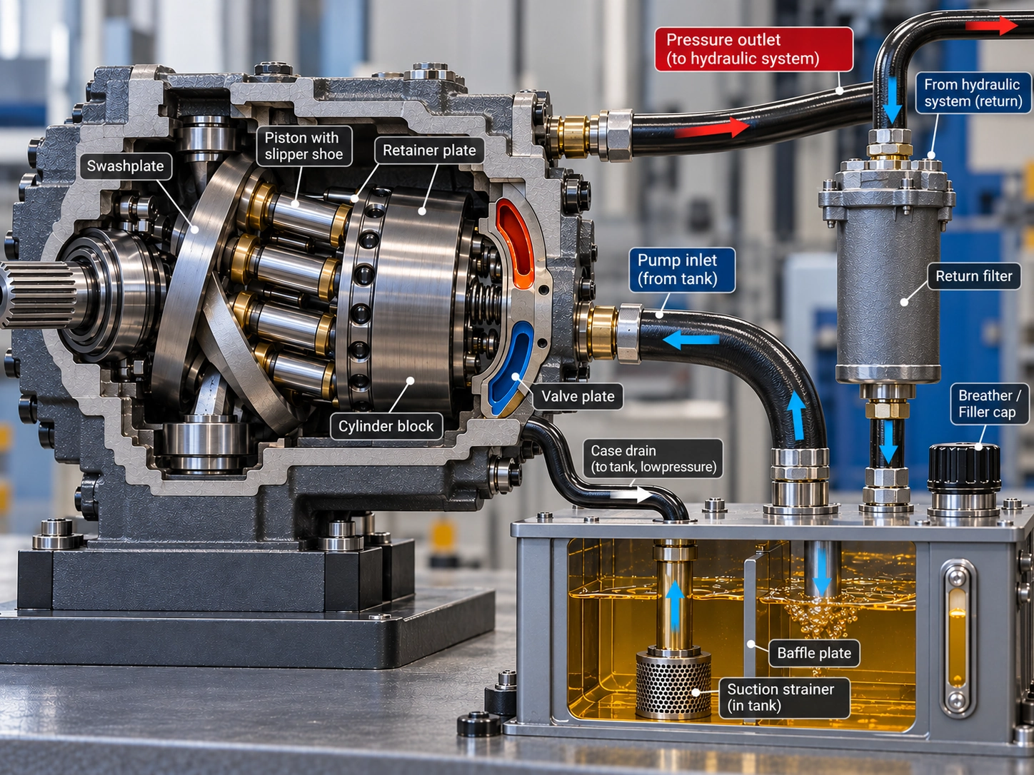
Where Contamination Damages an Axial Piston Pump
Particles become harmful when they interfere with the clearances and lubricating conditions between moving components. Bosch Rexroth identifies solid contamination trapped in piston-unit clearances as a potential cause of heat, interference, and mechanical damage. Its guidance also stresses correct inlet conditions, fluid viscosity, and case pressure. Bosch Rexroth's failure guidance therefore treats cleanliness as one operating requirement among several.
Valve Plate and Cylinder Block Wear
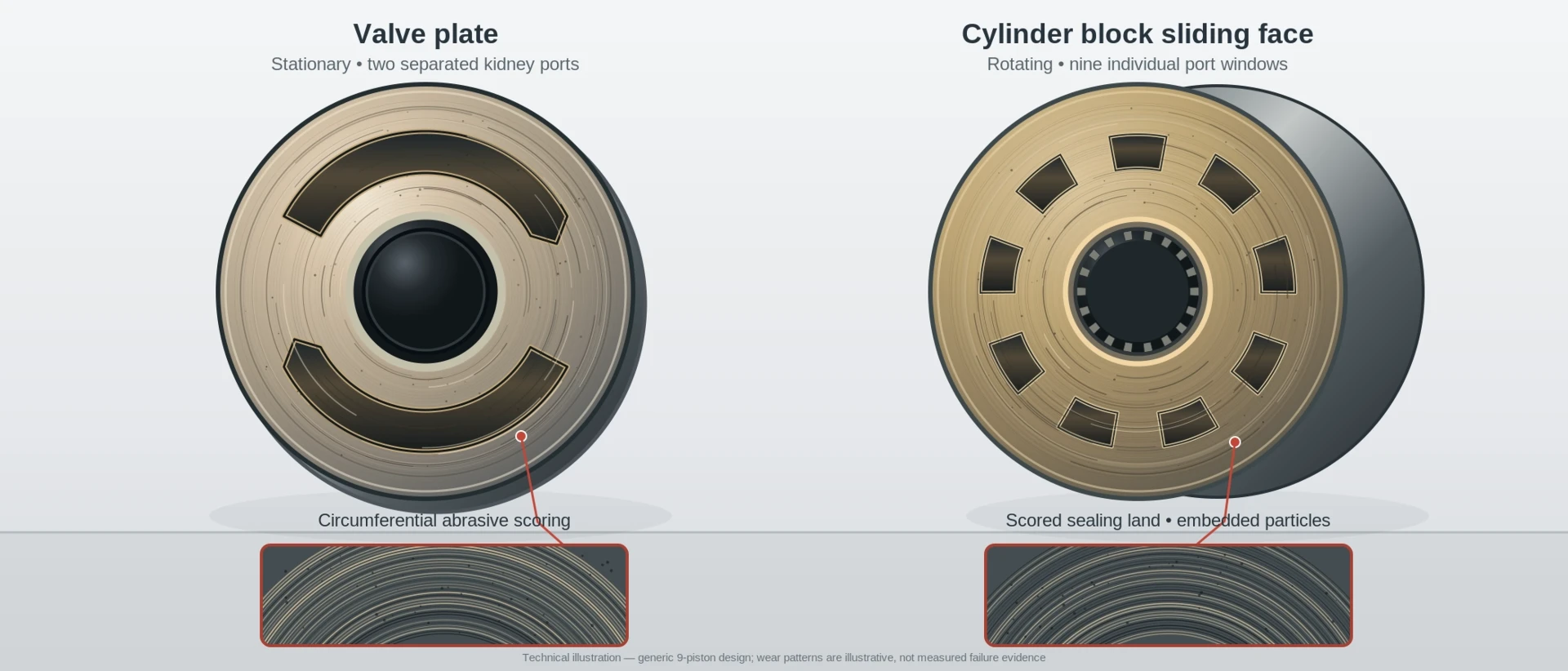
The cylinder block rotates against the stationary valve plate, which connects the cylinder bores to the inlet and outlet passages. These surfaces must maintain the intended geometry and lubrication while separating pressure regions.
Hard particles entering a lubricated sliding interface can cause abrasive scoring. Brendan Casey's piston pump failure analysis explains how particles comparable to an interface clearance can contribute to three-body abrasion.
As sealing surfaces deteriorate, leakage and heat generation may increase. However, scoring does not automatically prove particle contamination. Uneven contact, excessive pressure, or assembly problems can produce overlapping damage.
Piston Shoes and Swashplate Wear
In a swashplate-type pump, piston shoes slide against the swashplate. Their lubricated contact supports the working loads while allowing movement.
Particles can disturb these conditions and contribute to scoring or localized wear. The outcome depends on particle size and hardness, loading, and the condition of the lubricating film. Damage can also release additional wear debris into the system.
A useful inspection therefore examines the location and distribution of damage rather than relying on a general description such as "dirty oil."
Internal Leakage and Performance Loss
Wear may appear as reduced delivered flow, increasing heat, or deteriorating efficiency under comparable operating conditions.
Case-drain flow-the oil leaving the pump housing through its drain connection-can provide additional evidence where the pump design and OEM procedure permit it. An increase may indicate wear, but it must be interpreted at the specified pressure, speed, temperature, and displacement.
The guide to excessive case drain in piston pumps explains the diagnostic considerations. Neither case-drain flow nor temperature alone identifies the root cause.
What ISO 4406 Cleanliness Levels Mean for Piston Pumps
ISO 4406:2021 defines a method for coding solid particle contamination in hydraulic fluid. It does not prescribe one acceptable cleanliness level for every pump or predict operating life. ISO's public record identifies the 2021 edition as current following confirmation in 2026.
How to Read the Code
A three-number code such as 18/16/13 describes cumulative particle concentration classes:
| Code position | Particle-size threshold |
|---|---|
| First | ≥4 µm(c) |
| Second | ≥6 µm(c) |
| Third | ≥14 µm(c) |
Here, µm means micrometres; "(c)" identifies particle sizes associated with the ISO 11171 calibration convention. Each code represents a particle-count range per millilitre, rather than an exact count. Lower numbers mean fewer particles in the corresponding category.
Successive class ranges change by approximately a factor of two. This relationship describes contamination concentration, not a corresponding change in pump life. Parker's Handbook of Hydraulic Filtration, particularly its cleanliness tables, provides a manufacturer explanation of this coding system.
Why Published Recommendations Differ
The following values have different scopes and should not be treated as interchangeable specifications:
| Source | Published level | Scope and limitation |
|---|---|---|
| Chevron's January 2020 cleanliness recommendation compilation | 18/16/13 | Listed as a general piston-pump recommendation in a new-lubricant specification summary; not used here as a Bosch Rexroth specification |
| Danfoss Series 42 Technical Information, September 2025, printed p. 10 | 22/18/13 | Required fluid cleanliness for the documented Series 42 closed-circuit axial piston pumps |
The Chevron compilation is a secondary summary. Its Bosch Rexroth entry points to a separate cleanliness publication, R999000240, dated 2016. The 18/16/13 entry is used here only as a general benchmark in a secondary compilation, not as a verified requirement for a particular OEM model.
The Danfoss Series 42 manual supplies a series-specific requirement. Neither entry is a universal target for every installation.
Which Target Should the System Follow?
The system must satisfy the most demanding applicable component requirement, including sensitive controls and valves, while accounting for where cleanliness is measured.
Use this sequence:
- Identify the exact pump model and configuration.
- Check the applicable OEM documentation and its conditions.
- Review the requirements of other sensitive components.
- Establish a measurable system target and appropriate sampling locations.
Do not select a cleanliness code solely because it appears in a general reference table.
Where Filtration Protects the Pump-and Where It Does Not
Filter position determines which oil is cleaned before it reaches a component.
| Position | What it filters | Main limitation |
|---|---|---|
| Suction | Oil entering the pump served by that suction line | Restriction can compromise inlet supply |
| Return | Oil returning toward the reservoir | Does not intercept every particle before it reaches another component |
| Main pressure | Pump discharge flowing to downstream components | Oil has already passed through the pump |
| Charge pressure | Charge-pump discharge supplying the closed loop and relevant controls | Must preserve the required charge supply |
| Offline | Reservoir oil circulated through a separate filtration circuit | Does not intercept all locally generated contamination |
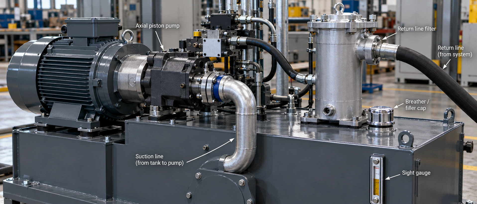
Suction Filtration and Inlet Restriction
A suction filter can intercept particles before they enter a pump, but its resistance must remain compatible with the inlet-pressure limits. Restriction can increase with contamination loading or cold, viscous oil.
The relevant pump must also be identified. Suction filtration on a closed-circuit transmission's charge pump is not necessarily equivalent to filtration on an open-circuit main pump inlet.
Danfoss Series 42 explicitly permits filtration before or after the charge pump. For its charge-pressure filtration arrangement, the manual specifies a 100–125 µm inlet screen. These details belong to that documented series, rather than to all piston pumps. See printed pp. 10 and 14–15.
For related symptoms, see hydraulic pump cavitation caused by inlet restrictions.
Return and Main Pressure Filtration
Return filtration helps remove contamination before oil re-enters the reservoir. Selection must accommodate the actual return flow and pressure conditions, including operating states that produce higher return flow.
Main pressure filtration protects components downstream of the pump, such as sensitive valves. It cannot remove particles before that same oil passes through the pump. Both locations can contribute to contamination control, but neither should be described as complete protection by itself.
Charge Pressure Filtration
In a closed-circuit transmission, the charge circuit replenishes losses and supplies relevant controls. Its filtration layout differs from a main discharge filter.
For Series 42, Danfoss states that charge-pressure filtration can reduce inlet vacuum during cold starts. Its printed p. 15 distinguishes partial-flow filtration using a non-bypass filter from full-flow filtration requiring a bypass valve. These configurations must not be combined into one general filter-selection rule.
Offline Filtration
Offline, or kidney-loop, filtration uses a separate pump and filter to clean reservoir oil. It can supplement the operating circuit when existing contamination removal is insufficient.
Its effect depends on removal performance, circulating flow, operating time, reservoir circulation, and continuing contamination entry. It cannot guarantee that particles generated near a component will be captured before causing damage.
Why Micron Ratings Alone Are Not Enough
A "10 µm filter" description does not specify how efficiently the element removes particles at that size. Selection also requires flow capacity, pressure-drop characteristics, contaminant capacity, and compatibility with the circuit.
Understanding Beta Ratio
The beta ratio compares upstream and downstream particle counts at or above the same specified size:
βx(c) = upstream particle count / downstream particle count
Removal efficiency = (1 − 1/β) × 100%
| Beta ratio, compared at the same specified particle size | Calculated removal efficiency |
|---|---|
| 2 | 50% |
| 75 | Approximately 98.7% |
| 200 | 99.5% |
| 1000 | 99.9% |
An illustrative rating of β₁₀(c) = 200 corresponds to 99.5% removal for particles at or above 10 µm(c) under the represented test conditions. It does not mean the element removes every particle at that size or guarantees a particular system cleanliness code.
Donaldson's beta-rating explanation describes this relationship. ISO 16889:2022 covers multi-pass evaluation of particle removal, contaminant capacity, and differential-pressure characteristics.
Can a Clogged Filter Damage a Pump?
Yes, if the resulting restriction compromises the pump's required oil supply. A restricted suction path can contribute to starvation and cavitation; where a bypass opens, oil can continue flowing without receiving the intended element filtration.
These are different failure paths. The outcome depends on filter location, circuit protections, and operating conditions, so clogging does not produce the same result in every installation.
Assess differential pressure at relevant temperature and flow. Cold oil and a loaded element can both increase resistance; a reading without its operating conditions is incomplete evidence.
What Bypass Operation Means
A bypass preserves a flow path around the element when its opening conditions are reached. Bypassed oil does not receive the intended filtration through that element.
Repeated or sustained bypass operation should not be treated as normal contamination control. Follow the assembly's indicator and maintenance instructions, and distinguish bypass settings from housing pressure ratings or element collapse limits.
How to Verify That Filtration Is Working
Verification requires oil results as well as filter specifications. A correctly rated element is not proof that the entire system meets its target.
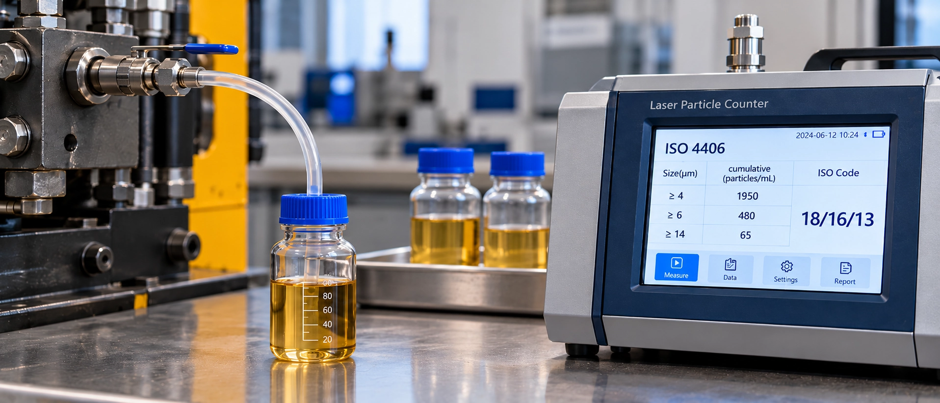
Take a Representative Sample
Parker's sampling guidance emphasizes representative fluid, clean containers, flushed sampling valves, and controlled handling. Apply those principles through the equipment's approved procedure:
- Choose an approved sampling point. Record its location and relationship to the filter.
- Use comparable operating conditions. Record operating state and oil temperature according to the OEM procedure.
- Use a suitable pre-cleaned bottle. Keep it closed until collection; avoid contaminating its interior or cap.
- Flush the sampling valve first. Follow the approved equipment or sampling-device procedure.
- Close and identify the sample promptly. Record the machine, fluid, date, location, and relevant operating conditions.
Parker's sampling procedure, printed pp. 32–33, provides the underlying handling guidance. Its historical timing and flushing quantities should not replace a machine-specific procedure.
Bottle testing measures collected oil; an appropriately installed online counter measures fluid passing through its sampling arrangement. Keep method and location consistent when reviewing trends. Parker's fluid-analysis handbook, printed pp. 32–33, discusses particle counting and laboratory analysis.
Compare Results with the Target
Compare each reported cleanliness-code position with the corresponding target. A cleaner result in one size category does not cancel an excessive count in another.
If a result is unexpected, review sample handling, operating state, and location before interpreting the change. Retest through the approved procedure where needed.
Review Differential Pressure and Contamination Sources
Record filter differential pressure alongside temperature and flow. Investigate abnormal readings and bypass indications, but do not use them as substitutes for particle counting.
Check breathers, filler caps, seals, hose changes, assembly cleanliness, storage, and transfer equipment. Replacing elements repeatedly will not resolve continuing contamination entry.
New hydraulic oil should not automatically be assumed to meet the system target. Particle counting also does not replace water, viscosity, or other fluid-condition analysis; these require separate assessment where relevant.
When Pump Damage Is Not Caused by Filtration
Poor filtration can contribute to wear, but pump damage requires a broader investigation.
| Possible cause | Relevant evidence |
|---|---|
| Particle contamination | Cleanliness history, particle characteristics, wear debris, and surface damage |
| Inlet restriction or cavitation | Inlet pressure, temperature, supply restrictions, and damage patterns |
| Excessive pressure | Operating pressure, transients, and loading history |
| High case pressure | Drain routing, restrictions, case-pressure limits, and seal condition |
| Incorrect assembly or contact | Component fit, alignment, locating features, and wear distribution |
The table is a diagnostic checklist, not proof of a cause. Bosch Rexroth's failure guidance supports checking cleanliness, inlet conditions, viscosity, and housing pressure; the case below illustrates the need to examine mechanical contact.
In Casey's investigation published in January 2017, valve-plate scoring was initially attributed to contamination. His teardown identified a locating dowel holding the plate away from its seating surface, producing uneven contact. As reported by the author, the cause was improper assembly.
This individual case does not establish how frequently such failures occur. It demonstrates why wear patterns and mechanical condition should be investigated before assigning a cause.
The guide to causes of hydraulic piston pump pressure loss provides related diagnostic context.
What Filtration Evidence Can Tell Us About Pump Life
A supplier-reported case can show improved cleanliness without proving a fixed extension of piston pump life.
In its 2017 hydraulic pump reliability case, Hy-Pro described a valve manufacturer reportedly losing approximately 25 pumps per year. The account did not identify the pump type.
The reported initial cleanliness was 22/21/19, against a target of 17/15/13. After reservoir sealing, breather installation, and an offline filter upgrade, the final sample after approximately 140 days was 12/11/7.
This is a filtration supplier's account, not an independent controlled piston pump lifetime study. Multiple measures changed together, and the published account does not provide a control group establishing their separate contributions.
The evidence supports checking contamination-control results. It does not establish that another installation will achieve the same outcome or a predictable increase in operating hours. That assessment would require operating history, comparable duty conditions, maintenance records, and failure evidence.
A Practical Filtration Check Before Repairing or Replacing a Piston Pump
Use the following record to identify missing evidence before deciding that filtration caused the damage.
| Check | Information to record | Evaluation basis |
|---|---|---|
| Pump identification | Model, series, nameplate and configuration | Applicable OEM manual |
| Circuit type | Open circuit or closed circuit | Hydraulic schematic |
| Required cleanliness | ISO 4406 target | Pump and sensitive component requirements |
| Actual oil cleanliness | ISO code, sample date and location | Particle-counting results |
| Filtration layout | Suction, return, pressure, charge or offline | Actual circuit arrangement |
| Filter specification | Particle rating, beta ratio and capacity | Element manufacturer data |
| Differential pressure | Reading, temperature and flow conditions | Filter housing and element limits |
| Inlet conditions | Inlet pressure, speed and oil temperature | Pump operating limits |
| Fluid condition | Viscosity, water content and relevant analysis | Fluid and OEM requirements |
| Wear evidence | Case drain, performance trends and inspection results | Model-specific diagnostic procedures |
If actual cleanliness exceeds the permitted contamination level, investigate filtration and contamination sources.
If the target is met but significant wear remains, investigate other operating or mechanical causes. A current clean sample also cannot establish the oil's condition throughout the pump's earlier service.
Where severe internal damage has occurred, cleaner oil will not restore worn surfaces. Repair or replacement should be accompanied by appropriate system cleaning and investigation of the original cause.
Safety note: Hydraulic systems can retain hazardous pressure. Sampling, testing, inspection, and component replacement must follow the equipment manufacturer's isolation, depressurization, and maintenance procedures. Pressurized connections should only be handled by qualified personnel using suitable equipment.
Preparing a Replacement Inquiry
Guangdong Sheungchak Hydraulic Technology Co., Ltd. provides hydraulic pump products for OEM and replacement applications.
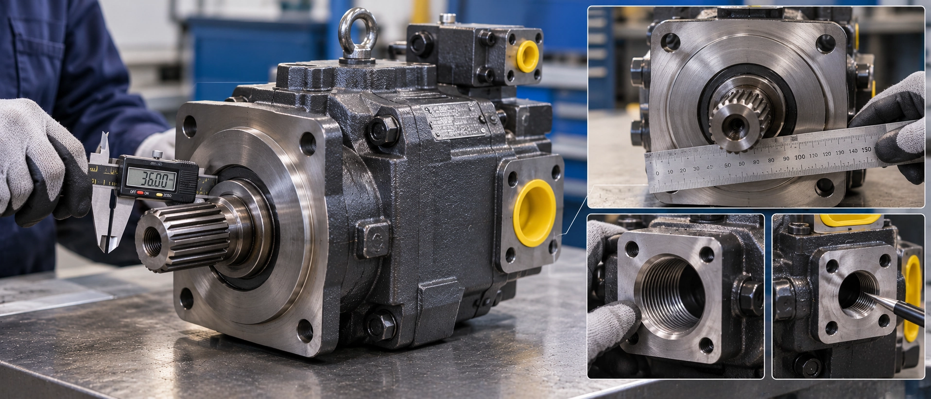
For a replacement inquiry, prepare the model code or nameplate photograph, displacement, pressure, speed, rotation, shaft, mounting, control configuration, and application requirements. Available oil-analysis and inspection findings can help describe the problem without replacing a failure investigation.
Review the hydraulic piston pump replacement options and submit a pump configuration inquiry with these details. Ask which available configuration matches the application and what additional information is needed to confirm compatibility.