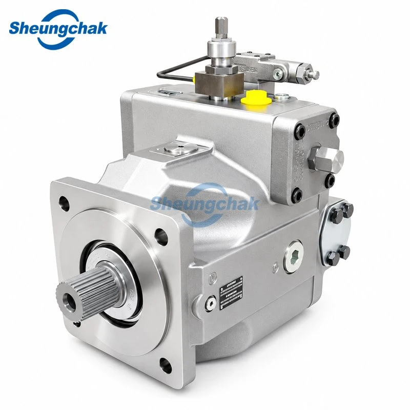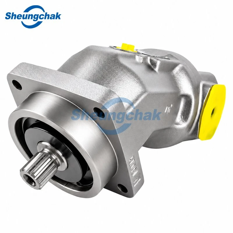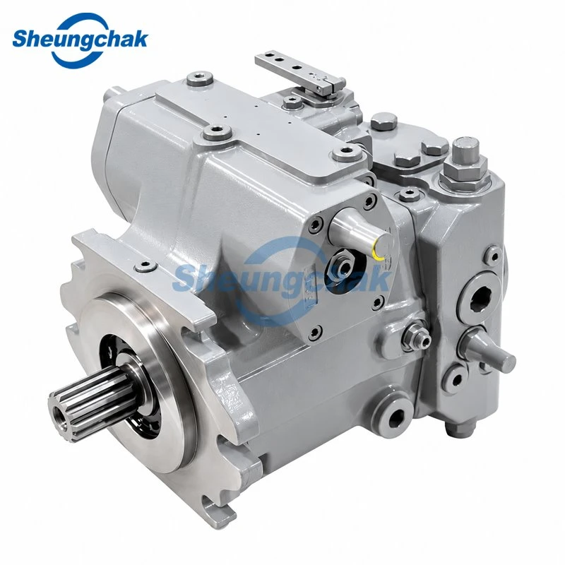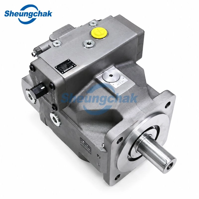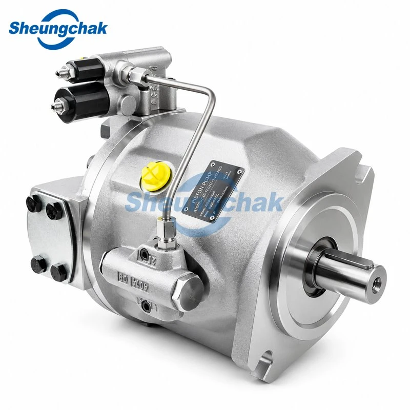

Stop guessing with industrial parts. Use this essential hydraulic pump replacement checklist to verify critical specs and ensure seamless system integration.
Sourcing industrial equipment replacements cannot rely on guesswork. A single incorrect parameter routinely causes system overheating or immediate mechanical failure. This hydraulic pump replacement checklist provides procurement teams and engineers with nine core specifications to confirm before issuing purchase orders. Verifying these exact details ensures seamless physical and functional integration for hydraulic gear pumps and other critical fluid power components.
Repair vs. Replacement: When to Order a New Pump
Replacement makes economic sense when repair estimates cross specific asset value thresholds and downtime penalties grow. The average lifespan of a well-maintained hydraulic pump reaches 6k-10k hours under normal industrial conditions. When components fail, procurement teams must evaluate whether rebuilding the unit justifies the material costs and operational delays. A standard rule of thumb sets the repair vs. replacement cost threshold at 50% to 60% of the unit price. Once the repair estimate crosses 50% of the market value, ordering a new unit generally provides better long-term reliability and warranty protection.
Financial calculations must also include the estimated cost of job site downtime. This cost typically ranges from $150 to $300 per hour depending on the operation. Replacing a pump usually takes two to six hours of labor for physical swapping and system commissioning. Because of this, extended repair delays compound operational losses rapidly. Procurement managers must weigh the immediate availability of a new pump against the lead time needed for a machine shop to source internal replacement parts and rebuild the damaged unit.
How to Identify Specs with Missing or Damaged Nameplates
Procurement personnel can rebuild missing specification data through original technical documentation and structured reverse engineering. Harsh plant conditions often wear away pump nameplates. This leaves maintenance teams without clear model codes or operating parameters. Gathering accurate specifications requires consulting original equipment manuals, hydraulic schematics, and dimensioned engineering drawings. High-resolution photographs of the pump housing, mounting interfaces, and control blocks help suppliers identify the base casting. Buyers should measure key external dimensions with precision tools and contact specialized manufacturers like Sheung Chak Hydraulics for reverse engineering verification.
Locate the original equipment manufacturer service manual to identify the baseline circuit requirements and the corresponding hydraulic schematic.
Measure the physical drive shaft, mounting flange, and port dimensions using digital calipers to establish the precise mechanical envelope.
Photograph the installed pump from multiple angles, ensuring all control valves and connecting fluid lines remain visible for context.
Submit the collected measurements, photographs, and system performance requirements to a qualified manufacturer for accurate component matching.
| SAE Mounting Standard | Pilot Diameter | Operating Parameter / Limit | Verification Method |
| SAE AA | 2.00″ | 110–140ºF normal fluid temp | Verify diameter with digital calipers. |
| SAE A | 3.25″ | 500 operating hours filter interval | Check pilot fit against pump bracket face. |
| SAE B | 4.00″ | 95% of rated maximum pressure | Measure pilot circle step on mounting flange. |
| SAE C | 5.00″ | 150ºF valve bypass threshold | Use precision micrometer on centering ring. |
| SAE D | 6.00″ | 400 bar (5,800 PSI) piston rating | Confirm bolt pattern matches pump snout. |
| SAE E | 6.50″ | 6k–10k hours average lifespan | Gauge pilot collar before ordering unit. |
| SAE F | 7.00″ | 10,000 psi maximum hose limit | Verify large frame mounting bore fitment. |
Checklist of nine specifications for replacing hydraulic pumps
Internal specification mismatches cause severe system damage. This happens even when replacement pumps look identical to the original units. Hydraulic gear pump replacement is the main focus for most industrial buyers. However, the same verification rules apply to complex variable displacement units. We will address piston and vane pump requirements only when necessary to explain critical operational differences that affect buying decisions. This checklist details hydraulic pump replacement specifications so buyers capture every necessary data point before contacting suppliers.
1. Manufacturer, Model Code, and Pump Type
A single changed letter at the end of a model code often points to entirely different internal controls or pressure settings. The original maker and complete model code provide the base for any replacement effort. Buyers verify this information directly from the equipment manual or the pump nameplate. Suppliers need the full code to match internal parts accurately. Choosing an incorrect pump type, such as putting a light-duty gear pump into a heavy continuous run, consistently leads to early fatigue failure.
Procurement teams must give the exact alphanumeric sequence to their vendors. Shortened codes drop vital facts about shaft seals, rotation direction, and displacement limits. When the original maker no longer builds that specific series, the complete model code allows engineering teams to match original performance curves to a modern equivalent. Ignoring minor characters in the part number often results in receiving a pump with standard seals when the job actually needs high-temperature viton elastomers.
2. Displacement, Required Flow, and Operating Speed Range
Matching displacement without checking the matching drive speed range often leads to weak fluid flow or destructive cavitation. Displacement measures the volume of fluid moved per revolution. Actual flow depends entirely on the operating speed. Buyers verify required flow by multiplying displacement by drive speed. This calculation ensures the resulting volume meets actuator needs. Suppliers need buyers to provide the actual operating speed of the motor or engine rather than just a maximum flow rate.
A common replacement error involves installing a pump with the right displacement but an incompatible speed rating. Driving this pump too fast starves the inlet and causes cavitation. On the other hand, driving a high-speed pump too slowly disrupts internal lubrication and slows system response. Engineers must confirm whether the machine needs full flow continuously or only during specific peak tasks across the duty cycle. Providing the minimum, normal, and maximum operating speeds allows the supplier to select a pump that maintains volumetric efficiency across the entire range.
3. Continuous and Peak Pressure Ratings
Operating a replacement pump below its required continuous pressure rating leads directly to cracked housings and rapid internal wear. Continuous pressure ratings set the normal working load the pump can hold indefinitely. Peak pressure defines the maximum brief spike allowed during relief events. Buyers check system relief valve settings to verify actual operating pressure. Suppliers need a clear view of the machine duty cycle to recommend the right housing materials.
Low pressure ratings cause fluid to leak past internal clearances. This action generates extreme heat and wears down gear faces early. Gear pumps handle standard industrial loads well. However, technical documents show a 400 bar (5,800 PSI) pressure capacity for heavy-duty piston pumps, making them necessary for extreme force applications. Procurement teams must never assume a cast iron pump matches the pressure rating of an aluminum model just because they share the same shape. Material strength determines the maximum safe system load.
4. Shaft Rotation Direction and Drive Compatibility
Installing a pump with the wrong rotation direction instantly builds reverse pressure that destroys the main shaft seal. Hydraulic pumps run in specific directions, either clockwise or counterclockwise. This direction depends on internal ports and bearing lubrication paths. Buyers find the required rotation by looking directly at the pump shaft end from the drive motor side. Suppliers require clear rotation markers because bidirectional pumps remain rare in high-pressure industrial uses.
If maintenance teams install a reverse-rotation gear pump, internal fluid dynamics push high-pressure oil directly into the low-pressure seal cavity. This causes an immediate seal blowout and heavy fluid loss. Some gear pumps allow field changes by taking apart the housing and turning the center section. However, this fix requires specific technical skill and voids factory warranties. Ordering the right rotation from the start avoids field modifications and stops catastrophic startup failures.
5. Drive Shaft Configuration and Dimensions
Physical shaft mismatches ruin the thin fluid film at the seal face, causing dry friction that burns out elastomers. The drive shaft carries mechanical power from the engine to the pump internals. Because of this, it must match the coupling dimensions precisely. Buyers must verify the spline count, flat key dimensions, and overall shaft diameter. We suggest taking measurements with a precision of 0.001 inches. Suppliers use this data to ensure the new shaft fits existing parts without loose play or forced binding.
When shaft fits are off, the resulting vibration breaks the microscopic oil film needed for smooth lubrication. This loss of fluid film lets dry friction create hot spots, which hardens the shaft seal and causes severe external leaks over time. Furthermore, forcing a slightly oversized splined shaft into a worn coupling puts heavy axial loads on the internal pump bearings. This drastically cuts the working lifespan of the new unit.
6. Mounting Flange and Installation Dimensions
Relying on visual similarity rather than standard flange dimensions causes mechanical misalignment, bad vibration, and broken shafts. The mounting flange centers the pump on the drive source. This keeps the drive shaft lined up straight with the power input. Buyers check fit by measuring the pilot diameter with calipers and reading the center-to-center distance of the bolt holes. Suppliers need these exact numbers to guarantee a direct bolt-on fit without custom adapter plates or equipment rework.
Failing to match the pilot diameter allows the pump to shift while running. This shift puts uneven loads on the shaft bearings, which leads to major mechanical breakdown. Even a slight angular misalignment wears out coupling inserts quickly and sends harmful vibrations through the entire hydraulic circuit.
| SAE Flange Standard | Pilot Diameter Specification |
| SAE AA | 2.00″ - Pilot diameter for SAE AA mounting flange |
| SAE A | 3.25″ - Pilot diameter for SAE A mounting flange |
| SAE B | 4.00″ - Pilot diameter for SAE B mounting flange |
| SAE C | 5.00″ - Pilot diameter for SAE C mounting flange |
| SAE D | 6.00″ - Pilot diameter for SAE D mounting flange |
| SAE E | 6.50″ - Pilot diameter for SAE E mounting flange |
| SAE F | 7.00″ - Pilot diameter for SAE F mounting flange |
7. Port Dimensions, Locations, and Sealing Interfaces
Incorrect port setups cause high suction resistance that ruins internal parts, or high-pressure leaks that lower efficiency. Inlet and outlet ports control how fluid enters and leaves the pump. These ports require exact matches in size, position, and thread standards. Buyers verify these points by measuring thread pitches or flange faces and checking whether ports sit on the side or rear of the body. Suppliers need exact interface types, such as SAE split flange, NPT, or BSPP, to keep buyers from using restrictive adapters.
Using an undersized inlet port makes fluid move too fast. This drops inlet pressure and forms vapor bubbles that eat away at internal metal surfaces. Adapters also add more leak paths to the circuit. In many cases, they push the pump body past the available installation space. Confirming port specifications ensures existing hoses bolt directly onto the replacement unit without causing unwanted flow restrictions or pressure drops.
8. Fluid Compatibility and Operating Temperatures
Running outside the specified temperature range changes fluid thickness, raising internal leakage and risking sticky valves across the system. Hydraulic pumps need working fluid for internal lubrication and cooling. Because of this, fluid compatibility is a critical replacement factor. Buyers check the current oil type and viscosity grade. At the same time, suppliers need to know expected room and operating temperatures. Industry observations show a 110-140ºF normal operating temperature range for most hydraulic systems.
When oil gets too hot, it thins out. This drops volumetric efficiency and weakens the protective oil film between moving parts. Furthermore, a 150ºF temperature threshold on valves and solenoids shows internal oil bypass or mechanical sticking. This heat demonstrates how an inefficient pump damages downstream parts. If the system uses fire-resistant fluids or water-glycol mixes, buyers must state this clearly. Standard nitrile seals break down quickly when exposed to specialized synthetic fluids.
9. Special Configurations (Multiple Pumps, Case Drains, Controls)
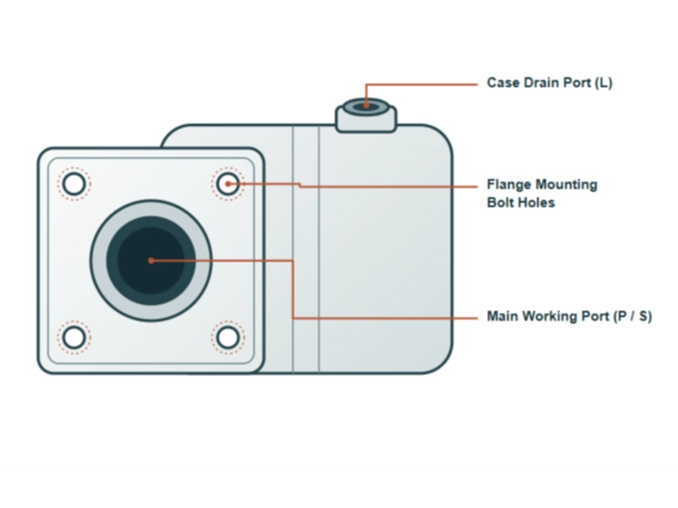
Blocked or undersized case drain lines push internal case pressure past structural limits, quickly blowing out shaft seals. Many industrial machines use tandem gear pumps or units with built-in control valves that need dedicated line routing. Buyers must inspect the current pump for secondary fluid lines, load-sensing ports, or external case drains. Suppliers need clear data on flow splits across multiple sections to ensure each stage of a tandem pump receives the right gear set.
A common failure in piston pumps and multi-stage gear setups occurs when technicians do not connect the case drain properly. This mistake lets bypassed oil build pressure inside the housing until the weakest part fails. For variable displacement units, procurement teams must verify whether the regulator uses pressure control, flow control, or electronic proportional mechanisms. Replacing a load-sensing pump with a standard pressure-compensated unit ruins the machine control logic. The equipment will not work despite a perfect physical fit.
Direct Interchangeability vs. Engineered Alternatives
Matching outer mounting surfaces does not guarantee matching internal performance under heavy industrial loads. Procurement teams must separate directly interchangeable replacements from alternatives that need engineering review. Directly interchangeable units match the original part in physical size, volumetric efficiency, material strength, and internal clearances. These pumps bolt into the system and deliver identical performance without adjustments to the motor or relief valves.
| Parameter / Component | Specification / Threshold | Operational Impact |
| SAE AA Flange | 2.00″ pilot diameter | Direct pilot alignment for sub-compact pumps |
| SAE A Flange | 3.25″ pilot diameter | Standard mounting engagement for light-duty units |
| SAE B Flange | 4.00″ pilot diameter | Precise housing positioning on medium-frame drives |
| SAE C Flange | 5.00″ pilot diameter | Critical dimensional match for mid-to-high displacement pumps |
| SAE D Flange | 6.00″ pilot diameter | Secures alignment on high-torque industrial machinery |
| SAE E Flange | 6.50″ pilot diameter | Frame tolerance limit for heavy continuous-duty equipment |
| SAE F Flange | 7.00″ pilot diameter | Exact bore interface for severe-service extra-large units |
| Heavy-Duty Piston Pump | 400 bar (5,800 PSI) | Maximum continuous structural pressure limit |
| Pump Pressure Output | 95% of rated maximum | Minimum acceptable delivery to avoid unit decommissioning |
| Operating Temperature | 110–140ºF | Target thermal range for optimal fluid viscosity |
| Valve / Solenoid Heat | 150ºF threshold | Symptom of internal bypassing, sticking, or excessive friction |
| Heavy-Duty Filtration | 500 operating hours | Mandatory fluid filter replacement service interval |
Alternatives needing engineering review may bolt onto the machine easily. However, they might use different gear shapes or bearing styles that change operating heat levels. Even when all nine general specifications match, internal design differences affect how the pump takes shock loads and dirty oil. Buyers should consult specialized manufacturers to secure exact matching capabilities and custom build options that maintain original machine reliability. A well-engineered alternative often improves upon the original unit by using modern bearings or stronger housings, as long as the supplier understands the job needs.
Supplier Evaluation Criteria and RFQ Template
Vetting suppliers on technical data and factory test records prevents the purchase of low-quality or incompatible replacement pumps. Buying teams must look past base price and lead times to ensure long-term plant stability. Good evaluation criteria include fit guarantees, full technical drawings, open factory inspection records, and real load testing data. Suppliers must also show clear part traceability and firm shipping dates to reduce job site delays. Using a structured request for quotation ensures suppliers receive all needed technical data upfront. This practice stops guesswork and cuts the risk of wrong shipments.
Target equipment make, model, and primary operating function.
Original pump manufacturer and complete alphanumeric model code.
Required displacement, operating speed range, and target flow rate.
Continuous operating pressure and peak system relief settings.
Shaft rotation direction viewed from the prime mover end.
Drive shaft dimensions including spline count or keyway measurements.
Mounting flange standard and exact pilot diameter measurement.
Port locations, thread standards, and sealing interface types.
Fluid type, viscosity grade, and expected operating temperature range.
Pre-Installation Checks and Commissioning Procedures
Installing a correctly specified pump into a dirty hydraulic system is the leading cause of early secondary failure. Getting the right pump is only the first step in a proper repair. Industry maintenance records show that 80% of hydraulic system failures stem from fluid contamination. Before bolting on the new unit, technicians must flush the fluid tank, clean all suction lines, and replace line filters. While official guidelines vary, common practice suggests a 500 operating hours recommended filter change interval for heavy-duty systems.
New pumps need approved startup steps. These include filling the case, venting air, and running an initial spin without load to build oil films. During final testing, operators check pressure response. Reaching a 95% of rated maximum minimum pressure output threshold shows the pump is ready for normal work. Unverified sources suggest some high-pressure hydraulic hoses can pass a 10,000 psi pressure threshold. Even so, standard commissioning tests must never run past the system relief valve setting.
Drain the main reservoir, flush all connecting lines, and install new filtration elements throughout the circuit to remove suspended particulate matter.
Mount the replacement pump, ensuring the drive shaft aligns perfectly with the prime mover coupling without forced interference or binding.
Fill the pump case with clean hydraulic fluid through the highest available port to prevent dry starting friction during the initial rotation.
Start the prime mover at the lowest possible speed without engaging actuators, allowing trapped air to bleed back to the reservoir before applying load.