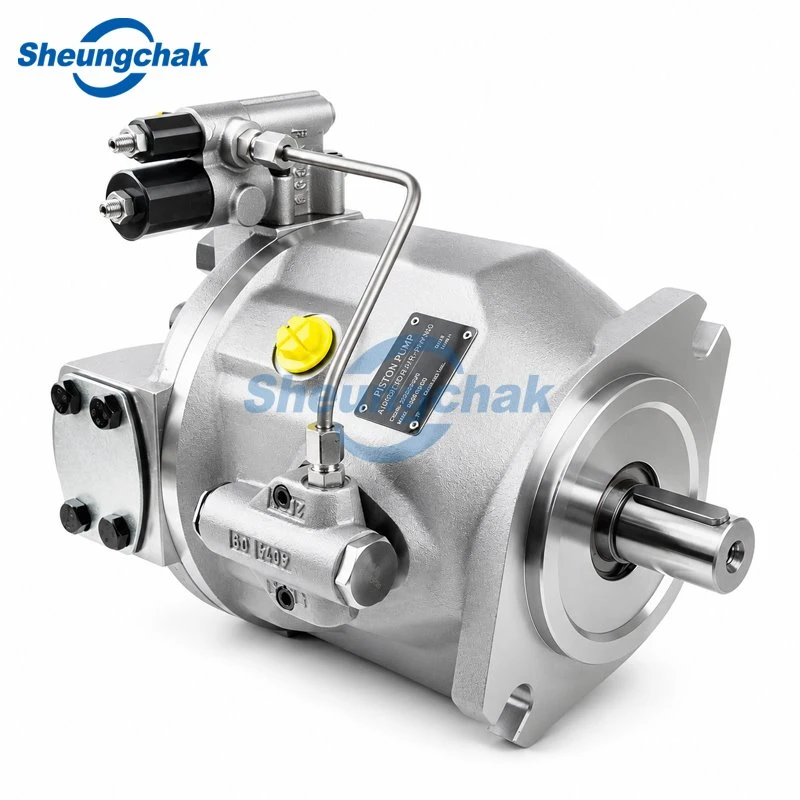

During operation, the cam on the fuel injection pump camshaft and the plunger spring force the plunger to reciprocate up and down, thus completing the pumping task. The pumping process can be divided into the following three stages:
① The total stroke L of the plunger's reciprocating motion is constant, determined by the cam's lift.
② The amount of fuel supplied per plunger cycle depends on the fuel supply stroke, which is variable and not controlled by the camshaft.
③ The start time of fuel supply does not change with the fuel supply stroke.
④ Rotating the plunger changes the end time of fuel supply, thereby changing the fuel supply quantity.
Domestic series of plunger-type fuel injection pumps: Domestic series of plunger pumps mainly include A, B, P, Z and I, II, III series. The series design is based on the different fuel supply requirements of the single-cylinder power range of diesel engines. It uses plunger stroke, pump-cylinder center distance, and structural type as a basis, and then combines them with different plunger diameters to form several types of fuel injection pumps with different fuel supply quantities in one working cycle, to meet the needs of various diesel engines. The working principle and structure of domestically produced fuel injection pumps are basically the same. Taking the type A pump as an example, we will introduce the structure and working principle of the plunger-type fuel injection pump. The plunger pump consists of four main parts: a distributor pump, a fuel quantity regulating mechanism, a transmission mechanism, and a pump body. It is intelligently controlled by a microprocessor, with an LCD display, and can communicate with a computer. It features stable working pressure, low pulsation, and convenient operation. It is widely used in biochemical, pharmaceutical, chemical, and environmental protection industries, meeting the requirements of these industries for continuous constant pressure and constant flow liquid delivery.