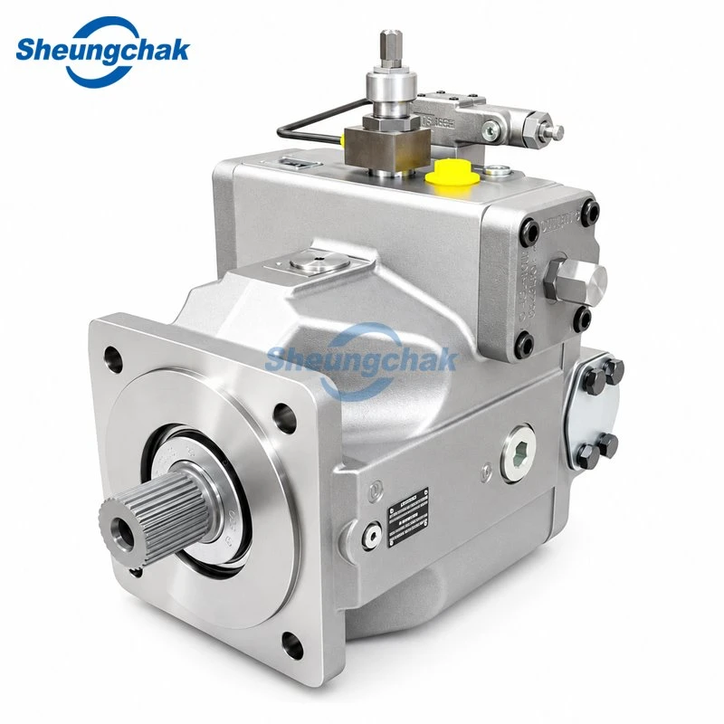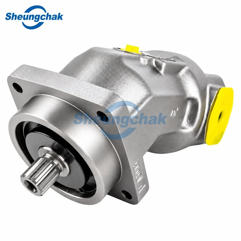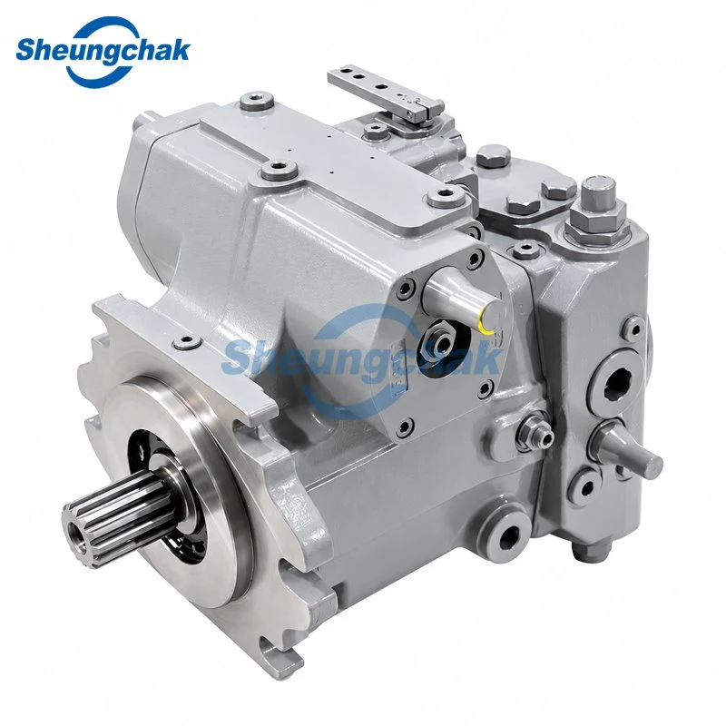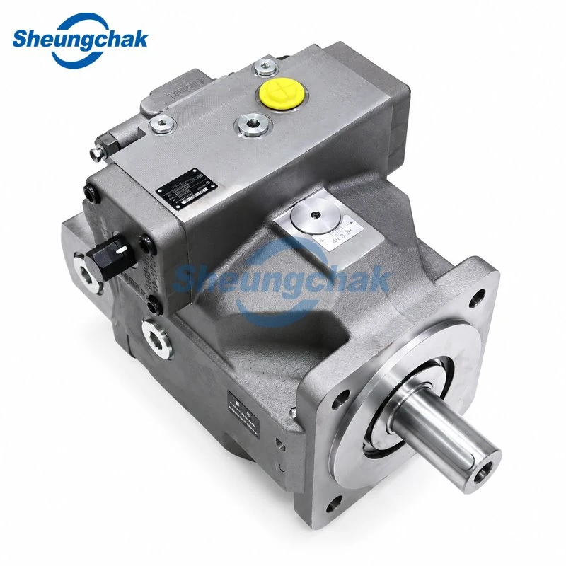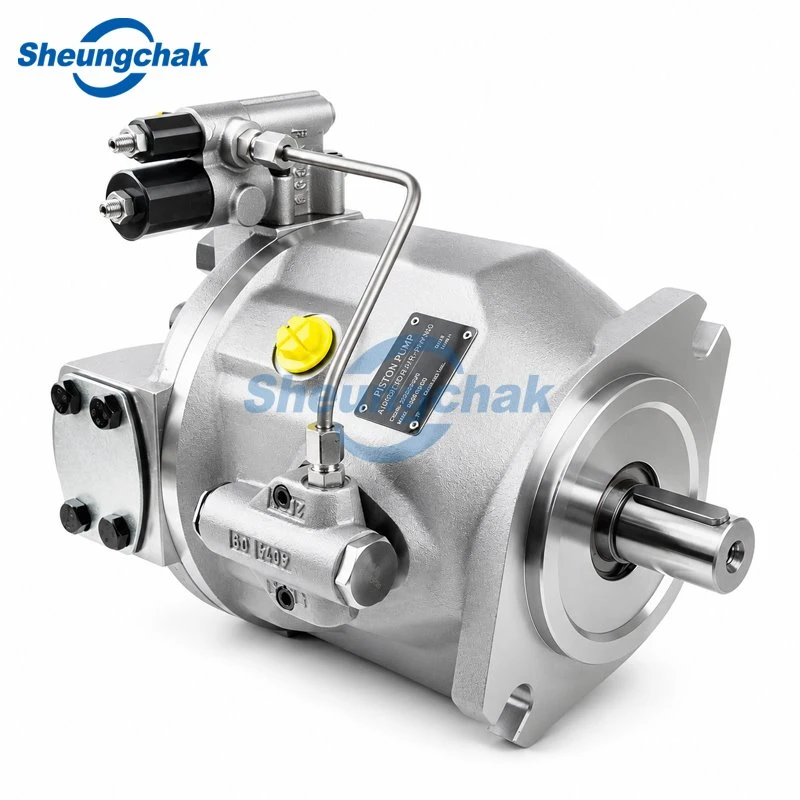

An A10VSO can be considered for an injection molding machine or industrial hydraulic system when its specific configuration matches the circuit, machine duty and installation conditions. The model family alone does not establish suitability. Start with the machine's pressure–flow–time requirements, then check the exact pump series, control function and operating limits.
This A10VSO application guide uses Bosch Rexroth Series 31 documentation as a technical reference. It does not establish the ratings or compatibility of another manufacturer's pump bearing a similar designation.
Where Does an A10VSO Fit in an Industrial Hydraulic System?
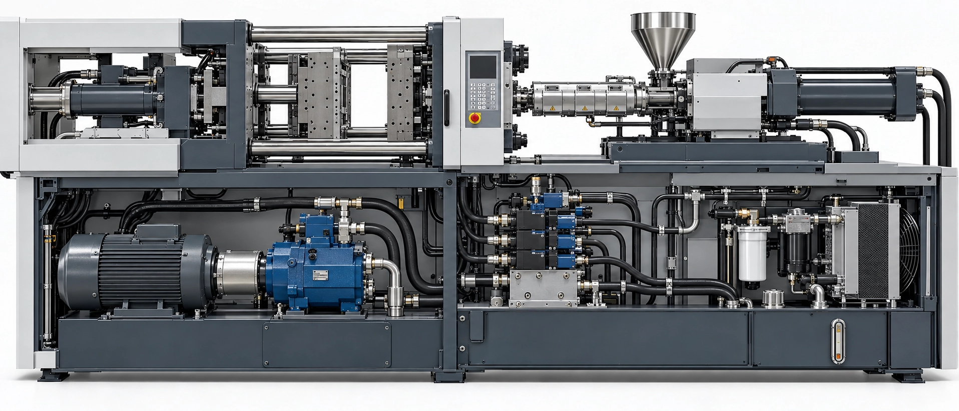
The referenced Series 31 instruction manual describes A10VSO as an open-circuit variable axial piston pump for stationary applications and distinguishes it from A10VO mobile applications. Similar designations should not be treated as interchangeable specifications. See the Bosch Rexroth Series 31 instruction manual, RE 92701-01-B/04.2018, sections 5.1–5.2, third-party-hosted copy.
Begin with the hydraulic schematic. Identify the candidate pump, the functions it supplies, the reservoir return, control connections and any auxiliary supply. If the circuit arrangement is unclear, review open-circuit hydraulic systems before comparing configurations.
For an injection molding machine, trace mold movement, injection, holding and screw recovery separately. Establish whether each task is supplied by this pump, another pump, an accumulator or a different drive. An accumulator-assisted movement, for example, requires a different assessment from a movement supplied directly by the candidate pump: identify both the movement demand and the pump's charging task.
The first decision is therefore which hydraulic task the pump must perform, rather than whether the machine belongs to a particular industry.
Define the Injection Molding Duty Before Selecting the Pump
A peak pressure and a maximum flow value are insufficient to describe the job. They may occur at different times. Assess operating points on a shared time base so that pressure, flow, drive speed and duration describe the same part of the cycle.
Record Pressure, Flow, Speed and Time
Use the actual machine sequence to complete a duty record. The rows below are recording prompts, not a prescribed injection molding cycle.
| Machine task to verify | Supply source | Pressure and measurement point | Flow and measurement point | Pump speed | Duration and overlap |
| Mold movement | Identify | Measure or document | Measure or document | Record | Record |
| Injection | Identify | Measure or document | Measure or document | Record | Record |
| Holding pressure | Identify | Measure or document | Measure or document | Record | Record |
| Screw recovery or another simultaneous task | Identify | Measure or document | Measure or document | Record | Record |
| Idle, unloading and transitions | Identify | Measure or document | Measure or document | Record | Record |
Attach fluid identification, oil temperature, machine settings, instrument details and the recording interval. Note whether the pressure and flow channels are synchronized and whether the measurement method can capture the transitions being assessed.
Use the record in the following order:
Identify concurrent demand. For each interval, establish which functions actually draw from this pump. Combine their flow requirements only where the circuit confirms a common supply; account separately for accumulator contribution and charging.
Translate the requirement to the pump. An actuator measurement is not automatically a pump-outlet requirement. Document the circuit path and the basis used to account for pressure losses, leakage or other flow paths.
Compare complete operating points. Check the required pressure, delivered flow, speed and duration together against the candidate configuration's documented limits.
Separate capacity from response. A pump that can reach a steady operating point has not necessarily demonstrated the required transition behavior.
Do not multiply a pressure peak from one part of the cycle by a flow peak from another and present the result as measured operating power. Likewise, an acceptable average does not establish that every transition is acceptable.
For an accumulator-assisted injection task, first verify whether this pump supplies the actuator during injection or charges the accumulator between events. If it only charges the accumulator, review the required charging pressure, replenishment volume and available charging time against the pump's duty. If it also supplies concurrent functions, include their verified demand over the same interval. If the schematic does not establish these paths, obtain that evidence before confirming capacity.
Separate Measured Requirements from Assumptions
Label every input as measured, specified by the machine builder, calculated or assumed. A controller setpoint is a command; it is not evidence that the hydraulic output reached that value.
The initial review should produce one of three outcomes:
The duty is sufficiently documented for comparison with supplier limits.
Supply paths, synchronized measurements or applicable limits remain unclear.
A verified requirement exceeds a documented limit or conflicts with the control arrangement.
If records are unavailable, prepare a provisional review from machine documentation and identify the measurements still needed. Do not substitute a generic pressure or flow figure based on machine tonnage.
Match the Control Function to the Machine Circuit
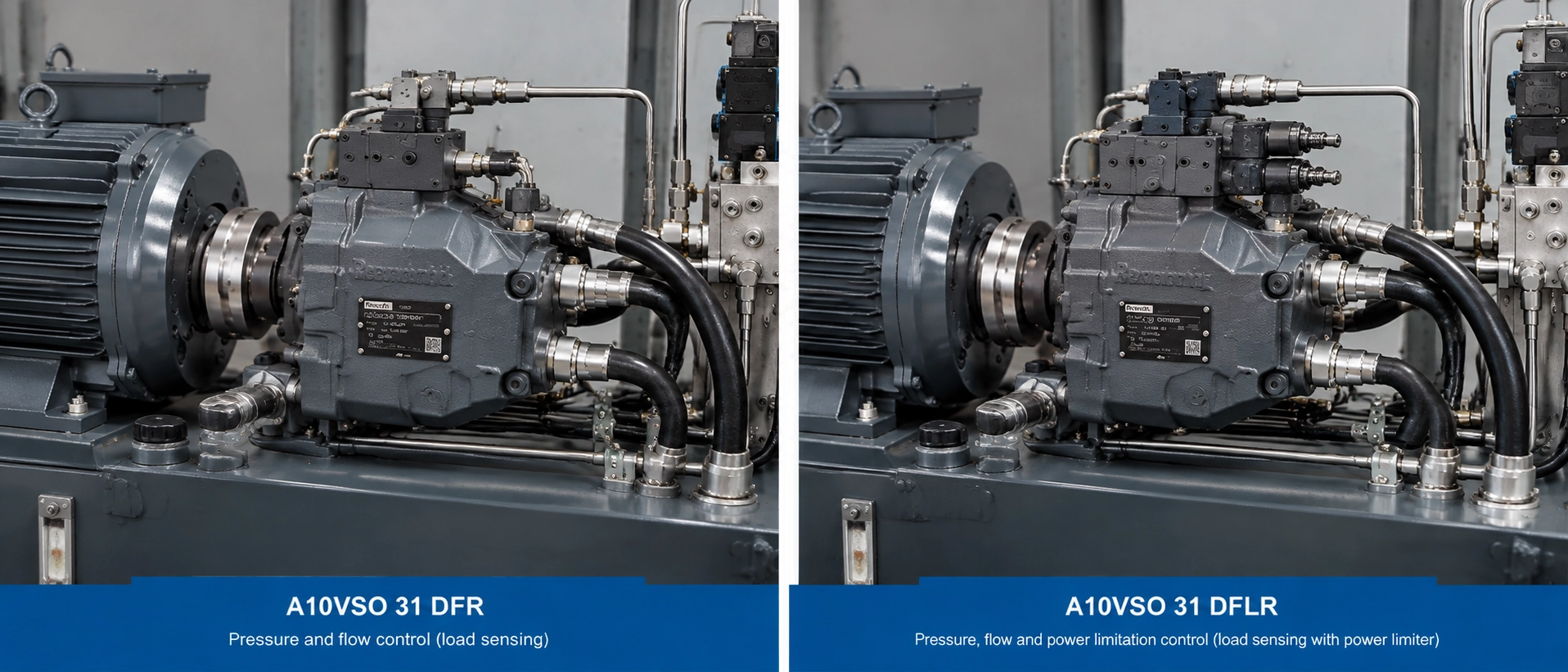
Select the control task before interpreting the abbreviated control code. A code identifies a configuration to investigate; it does not establish complete machine compatibility.
Hydraulic Control Requirements
| Machine requirement | Configuration to investigate | Evidence needed before confirmation |
| Pressure regulation | Applicable pressure controller, such as DR | Required pressure behavior, circuit arrangement and settings |
| Pressure and flow regulation | Applicable pressure–flow controller, such as DFR or DFR1 | Metering arrangement, signal connections and external unloading provisions |
| Pressure and flow regulation with a power constraint | Applicable pressure–flow–power controller, such as DFLR | Drive capability, settings and pressure–flow operating points |
| An electrical pressure command | Applicable electrohydraulic pressure control | Electrical interface, command characteristics, feedback and system requirements |
For the referenced Series 31 program, DFR1 has no internal unloading path between X and the reservoir; the valve system must provide sufficient LS/X-line unloading. Check the actual schematic before treating DFR and DFR1 as interchangeable. The relevant source is the Bosch Rexroth data sheet RE-A 92711/04.2017, page 15, third-party-hosted copy.
A DFLR review also needs the available drive power and torque across the required speed range. A power-control designation does not establish that the selected motor, coupling or through-drive arrangement can support the machine duty.
Use the documentation matching the actual configuration when checking connections and settings.
Pressure regulation does not replace overpressure protection. The Series 31 data sheet, RE-A 92711/04.2017, page 48, requires a pressure relief valve in the hydraulic system. Verify the protective arrangement against the machine design; a DR pressure setting alone does not establish system safety.
When System-Level Control Needs Separate Verification
An electrical pressure command does not establish that the machine can follow a required pressure or flow trajectory. Define the required response, allowable deviation and verification method for the complete pump, valve, sensor, controller and drive arrangement.
Bosch Rexroth's SY(H)DFE system overview describes integrated electrohydraulic control for A10 and A4 pump types. It illustrates the distinction between a pump control option and a configured control system; it does not demonstrate that an independently supplied pump includes those functions.
A static pressure test cannot establish transition accuracy, flow tracking or the performance of the complete injection molding cycle.
Check the Operating Envelope for Industrial Machinery
For a hydraulic power unit or machine tool, replace the injection molding rows with the actual equipment tasks. Keep the same assessment method: identify supply paths, simultaneous demand, operating duration and required control behavior.
Screen Flow and Drive Requirements
For an initial geometric flow calculation:
Qth = Vg × n / 1000
Here, Qth is in L/min, Vg is the operating displacement in cm³/rev, and n is drive speed in rpm.
Theoretical example: assume an operating displacement of 71 cm³/rev and a speed of 1,500 rpm:
Qth = 71 × 1500 / 1000 = 106.5 L/min
This calculated result excludes volumetric losses. It is neither a measured machine output nor evidence that a particular pump configuration is suitable.
Use applicable performance data or measurements to establish delivered flow at the required pressure, speed, temperature and fluid conditions. If volumetric efficiency is documented for that operating point, delivered flow can be estimated as Qactual = Qth × ηv. Do not insert an assumed efficiency as though it were verified.
Hydraulic output power is:
Phyd = Δp × Qactual / 600
Here, Phyd is in kW, Δp is the pump pressure rise in bar, and Qactual is the corresponding delivered flow in L/min.
In a separate hypothetical calculation, unrelated to the preceding flow example, a pressure rise of 200 bar at an assumed delivered flow of 100 L/min gives:
Phyd = 200 × 100 / 600 ≈ 33.3 kW
This is hydraulic output power, not the required motor nameplate rating. Pump shaft input also includes losses:
Pshaft = Phyd / ηt
Use verified total efficiency for the operating point, then assess motor capability, speed-dependent torque, starting and transition loads, coupling limits and auxiliary pump loads. Where efficiency or drive data are missing, leave the drive match unconfirmed. The Series 31 data sheet, page 9 distinguishes flow, torque, power and efficiency in its calculation relationships.
Apply the screening results as follows:
Verified delivered flow is insufficient: reassess displacement, permissible speed or the supply arrangement; do not treat theoretical flow as delivered capacity.
Required shaft power or torque exceeds the drive's documented capability: revise the drive or candidate configuration before confirming the match.
Efficiency, delivered-flow or drive data are missing: keep the match unverified and obtain the missing data.
The documented operating points satisfy the flow and drive checks: continue with pressure-duration, installation and response verification; this screening alone does not confirm the application.
Check Pressure Together with Duration
For mineral-oil-based fluids, Bosch Rexroth RE-A 92711/04.2017, page 6, lists 280 bar nominal pressure and 350 bar maximum pressure, with a 2 ms single operating period and 300 h total operating period for maximum-pressure operation. These historical Series 31 limits are not ratings established for Sheungchak's supply. Other fluids require applicable values.
Compare the pressure trace with every applicable pressure and time restriction. The maximum figure is not a continuous operating target, and the cumulative allowance does not override the single-period restriction. Confirm that the sensor response, acquisition rate and recording method can resolve the pressure events being assessed. A slow recording or an ordinary gauge reading cannot establish compliance with a millisecond-scale restriction. If the measurement system cannot resolve the event, keep pressure-duration compliance unverified; do not infer that no limit was exceeded.
| Review item | Evidence needed |
| Pressure and time | Pressure trace, event duration and applicable operating restrictions |
| Flow and speed | Delivered-flow data for each required operating point |
| Simultaneous demand | Common-supply tasks and any accumulator contribution |
| Drive capacity | Motor, shaft, coupling and auxiliary-load information |
| Holding and idle | Required pressure, flow and duration during low-demand operation |
| Transitions | Response criteria and verification records |
If a verified requirement falls outside the candidate's limits, identify a different configuration, circuit arrangement or pump family for review. Final selection requires configuration-specific evidence.
Confirm the Installation Conditions That Can Change Suitability
A duty match remains provisional until the installation is checked under the expected starting and operating conditions.
For the same historical data sheet, the standard inlet reference is 0.8 bar absolute minimum, subject to speed and displacement. Case pressure at L/L1 must remain at or below 2 bar absolute and no more than 0.5 bar above inlet pressure. These are version-specific references.
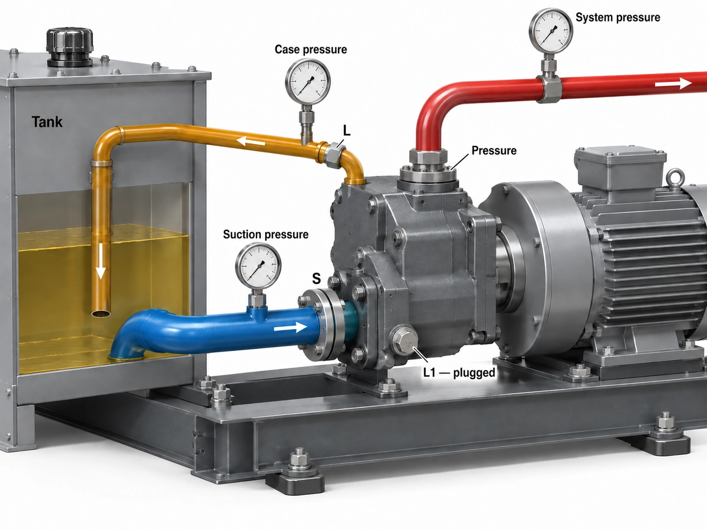
Measurements must be planned and performed by qualified personnel using appropriately rated instruments and machine-approved test points under the machine builder's procedures. Before connecting or removing test equipment, isolate the machine, secure it against restart and verify that the relevant components, including stored-pressure sources, are depressurized. Do not loosen connections while the system is pressurized. The Series 31 instruction manual, RE 92701-01-B/04.2018, sections 2.4–2.6, sets out personnel and pressure-safety requirements.
Record measurements at the relevant pump ports. A reservoir-level estimate or a pressure measured elsewhere in a shared return line does not establish the pressure at the pump connection.
Check the installation as follows:
Inlet: compare pressure at S with the applicable speed, displacement and fluid conditions, including starting conditions.
Case drain: compare L/L1 pressure with both the absolute limit and the permitted difference from inlet pressure under corresponding conditions.
Pressure reference: distinguish absolute from gauge readings before making comparisons; document any conversion basis.
Fluid: identify the fluid, temperature and viscosity range, seal compatibility and required cleanliness.
Mechanical interfaces: verify rotation, shaft, flange, coupling, ports and any through-drive arrangement.
Filling and restart: use the installation-position, filling, venting and recommissioning requirements applicable to the unit.
The Series 31 instruction manual, installation and commissioning chapters addresses these installation and restart requirements. A previously functioning installation is not sufficient evidence that a replacement configuration meets them.
What Remains Unverified in Your Application?
Use this table to record the decision status, then assemble the supporting documents in the next section. Select one status for each requirement and attach its evidence. "Unverified" means evidence is missing; it does not mean the requirement has passed or failed.
| Requirement | Confirmed | Unverified | Not satisfied | Evidence or next action |
| Exact model, series and document revision | □ | □ | □ | Nameplate photo; complete code; matching document revision |
| Circuit and control compatibility | □ | □ | □ | Schematic revision; signal paths; unloading provisions |
| Overpressure protection and measurement safety | □ | □ | □ | Protective circuit; approved test plan; rated instruments; qualified personnel |
| Pressure–flow–time duty | □ | □ | □ | Synchronized records; measurement points; operating conditions |
| Flow and drive requirements | □ | □ | □ | Delivered-flow basis; efficiency data; motor and torque checks |
| Mechanical interfaces | □ | □ | □ | Drawings; rotation; shaft, flange and coupling details |
| Fluid, inlet and case-drain conditions | □ | □ | □ | Fluid record; port measurements; pressure reference |
| Dynamic behavior, where required | □ | □ | □ | Acceptance criteria; test method and results |
Record an evidence reference, review date and responsible person for each completed row. For an unverified or unsatisfied item, identify the missing document, measurement or required change.
Do not describe the application as confirmed while a critical requirement remains unverified. A configuration review also does not replace machine-builder validation, applicable installation instructions or commissioning checks.
Prepare an A10VSO Application Review
Prepare one package containing:
Clear nameplate photographs and the complete model code.
The hydraulic schematic, including the candidate pump and any other supply sources.
Pressure, flow, speed and timing records with measurement locations, fluid conditions, data-quality labels and measurement-system response details.
Control requirements, electrical interfaces and required transition or tracking criteria.
Drive information, mechanical drawings and auxiliary pump details.
Installation layout, inlet and case-drain measurements, and fluid identification.
The completed status table, protective-circuit information, approved test plan and unresolved requirements.
Use the A10VSO product and configuration information page to prepare a configuration inquiry. Ask which configurations and matching technical documents can be provided, and what additional information is needed to compare them with your requirements.
Treat a product inquiry, a documented configuration comparison and machine acceptance as separate steps. Agree on the supplier's actual support scope before assigning any system-validation responsibility.