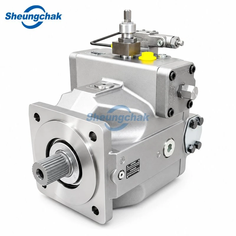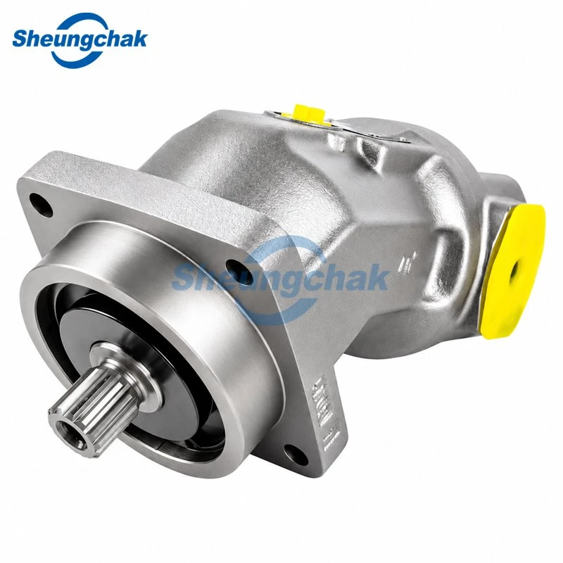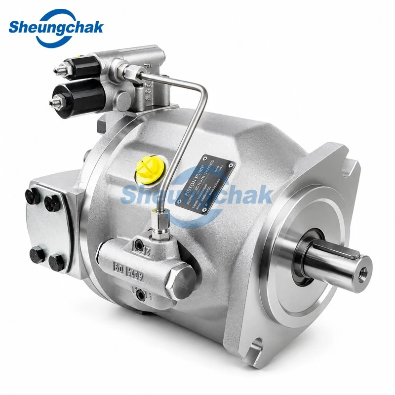

An A2FM application should be evaluated against the driven function, required torque and speed, operating cycle, and supporting hydraulic circuit. Displacement alone cannot establish whether a motor suits a travel drive, winch, or replacement installation.
A2FM is Bosch Rexroth's fixed-displacement, bent-axis axial piston motor family for hydrostatic drives in open and closed circuits. Fixed displacement describes volume per revolution, not constant operating speed. Output speed depends on flow and displacement; torque depends on pressure difference and displacement. See the Bosch Rexroth Africa A2FM product explanation.
This guide uses Bosch Rexroth documents as engineering references. They do not establish the performance or interchangeability of a separately supplied replacement motor. Selection approval requires evidence applicable to the exact unit.
Key Takeaways
- Define the load and operating cycle before choosing displacement.
- Check each size and configuration against its applicable document revision.
- Assess starting, smooth low-speed motion, and load-driven operation separately.
- Confirm the circuit, braking arrangement, installation, and interfaces before approving a motor.
Define the Drive Task Before Choosing a Size
Start with what the machine must do. "Mobile machinery" does not describe the requirements well enough: vehicle propulsion and controlled winch lowering involve different operating conditions.
Prepare an application description covering:
- The driven component and gearbox or coupling.
- Required starting torque, running torque, and speed range.
- Duration and frequency of each operating condition.
- Conditions in which gravity or inertia can drive the motor.
- Hydraulic circuit, installation position, and fluid conditions.
For a winch, specify line pull, effective drum radius, rope speed, and whether the function includes lifting, lowering, or holding. For travel, specify tractive demand, vehicle speed, gearing, gradients, and deceleration requirements.
The result should be a set of measurable operating points. A candidate remains unresolved until those points and its interfaces have been checked against applicable documentation.
Match the Motor to Travel or Winch Duty
Travel drives
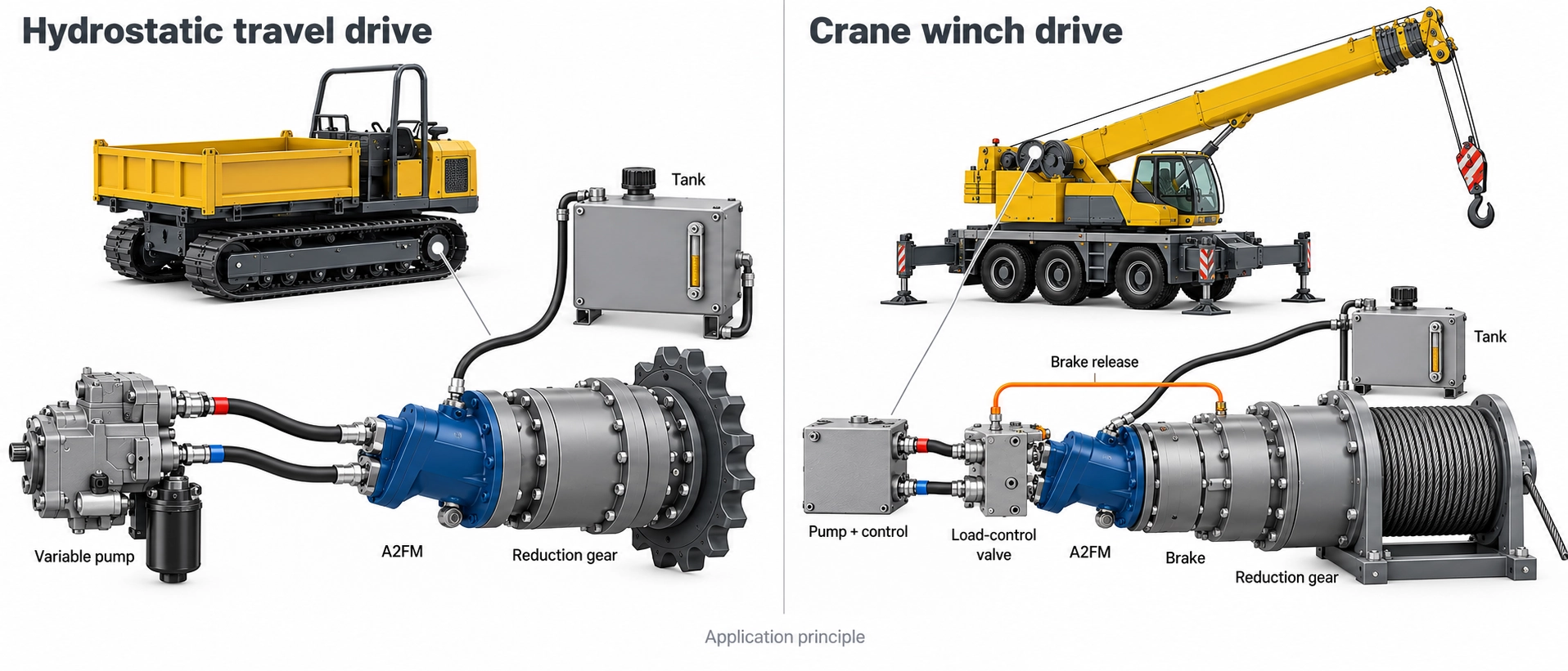
Separate starting, sustained travel, reversal, and deceleration. Translate the required tractive effort and vehicle speed through the final drive into motor-shaft torque and speed.
Treat downhill travel as a distinct condition. Propulsion capability does not by itself demonstrate controlled deceleration when the vehicle drives the motor.
The related guide to closed-circuit mobile drive applications provides pump-side context. It does not establish that every A4VG installation uses an A2FM motor.
Winch drives
Record effective drum radius across the intended rope layers, gearbox information, required line pull, and rope speed.
Lifting and lowering are different operating conditions. During lowering, the load can drive the motor, so the review must include load control and brake sequencing.
Bosch Rexroth's September 2007 data sheet includes wheeled-excavator travel and crane-winch circuit examples. These are manufacturer application examples, rather than customer installation records or approval of every machine in those categories: RE 91001/09.07, third-party-hosted manufacturer PDF.
| Function | Inputs to establish | Decision to resolve |
|---|---|---|
| Vehicle travel | Tractive demand, gearing, speed, gradients, reversals | Can the complete drive meet propulsion and deceleration requirements? |
| Winch lifting | Line pull, drum radius, gearing, lifting speed | Can the motor meet starting and running demand throughout the cycle? |
| Winch lowering | Load, lowering speed, load-control circuit, brake sequence | How will a load that drives the motor be controlled? |
Build a Motor-Shaft Duty Profile
Record operating points separately
Do not combine the highest torque from one condition with the highest speed from another unless they actually occur together.
Use a separate row for each operating condition:
| Operating condition | Required motor torque, N·m | Motor speed, rpm | Duration | Frequency | Additional information |
|---|---|---|---|---|---|
| Starting | Enter requirement | Enter requirement | Enter time | Starts per cycle | Breakaway load and acceleration |
| Normal operation | Enter requirement | Enter requirement | Enter time | Cycles per hour | Sustained load |
| Highest required speed | Enter simultaneous torque | Enter requirement | Enter time | Occurrences per cycle | Available flow |
| Reversal | Enter requirement | Enter speed transition | Enter time | Reversals per cycle | Inertia and control sequence |
| Load-driven operation | Enter requirement | Enter requirement | Enter time | Occurrences per cycle | Lowering or downhill condition |
Satisfying calculated running torque does not establish starting capability. Likewise, rotation at a low speed does not demonstrate acceptable motion uniformity.
Relate flow and pressure difference to output
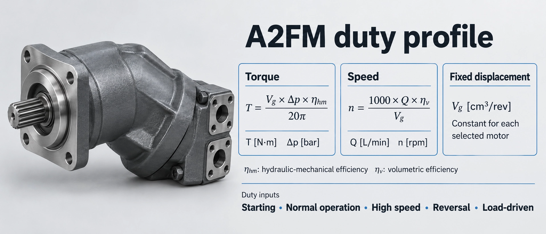
For motor operation, the relationships in Bosch Rexroth's Series 6x data sheet are:
Speed:
n = 1000 × Q × ηv / Vg
Output torque:
T = Vg × Δp × ηhm / (20 × π)
| Symbol | Meaning | Unit |
|---|---|---|
| n | Motor speed | rpm |
| Q | Motor inlet flow | L/min |
| Vg | Geometric displacement | cm³/rev |
| Δp | Pressure difference across the motor | bar |
| T | Output torque | N·m |
| ηv | Volumetric efficiency | Dimensionless |
| ηhm | Hydraulic-mechanical efficiency | Dimensionless |
Use the exact geometric displacement and applicable efficiency data. The source is Bosch Rexroth RE 91001/2019-09-17, page 5, third-party-hosted data sheet. Although the hosting URL says "service manual," the document identifies itself as a data sheet.
Illustrative calculation, not a product rating: a hypothetical 100 cm³/rev motor receiving 100 L/min at a pressure difference of 250 bar would have these ideal, loss-free outputs:
- Speed: 1000 × 100 / 100 = 1000 rpm.
- Torque: 100 × 250 / (20 × π) ≈ 398 N·m.
These values illustrate the relationships. They do not predict actual output, starting behavior, or compliance with operating limits.
Worked example: convert a winch requirement into shaft demand
Consider a hypothetical steady lifting point with:
| Input | Assumed value |
|---|---|
| Line pull | 20,000 N |
| Effective drum radius | 0.20 m |
| Rope speed | 0.20 m/s |
| Reduction ratio | 20 motor revolutions per drum revolution |
For this calculation only, ignore gearbox and motor losses, acceleration, and other dynamic loads.
Drum torque is:
20,000 × 0.20 = 4000 N·m
Drum speed is:
0.20 × 60 / (2 × π × 0.20) ≈ 9.55 rpm
With the stated reduction ratio, motor speed is:
9.55 × 20 ≈ 191 rpm
Ideal motor torque is:
4000 / 20 = 200 N·m
The resulting ideal steady lifting point is approximately 200 N·m at 191 rpm at the motor shaft.
This is a conversion of hypothetical requirements, not a motor recommendation. Actual lifting torque must account for transmission losses and dynamic demand. Starting, other rope layers, lowering, holding, and braking require separate checks. Use gearbox data applicable to the direction of power transfer.
Check the Complete Operating Envelope
Pressure limits depend on size and conditions
The family's highest advertised pressure is not a rating for every motor.
For historical reference, Bosch Rexroth's June 2012 Series 6 data sheet lists:
| Size group | Nominal pressure, bar absolute | Maximum pressure, bar absolute |
|---|---|---|
| 5 | 315 | 350 |
| 10–200 | 400 | 450 |
| 250–1000 | 350 | 400 |
These values belong to RE 91001/06.2012, page 1, third-party-hosted manufacturer data sheet. Maximum pressure is subject to the document's operating restrictions; it is not an unrestricted continuous rating.
Pressure difference and port-pressure compliance are separate checks. Use pressure difference to calculate torque. Compare working-port pressures A and B, their sum where specified, pressure duration, and minimum inlet pressure during pumping or overrunning operation with the applicable limits. Distinguish absolute from gauge pressure; differential pressure alone cannot establish compliance.
For every duty point, record the applicable limits and document revision. Include permitted speed, pressure duration, and any conditions associated with the selected configuration.
Low-speed motion needs its own acceptance criterion
The June 2012 document distinguishes unrestricted minimum rotational speed from uniform motion. Where uniformity is required, it specifies that speed must not fall below 50 rpm, within that document's scope.
This is not a universal threshold for all A2FM series or replacement products. It also does not prove that every application's motion-quality requirement will be satisfied at or above that speed.
Define the acceptable creeping or positioning behavior, then obtain applicable evidence or an application test.
Check the motor-and-valve assembly
A valve-equipped version needs assessment as a complete assembly. For counterbalance-valve versions, verify valve type, permitted inlet flow, pressure limits, and motor-to-valve matching against the September 2019 data sheet and the exact assembly drawing. Bare-motor ratings do not establish assembly compliance.
Classify each check as:
- Supported: applicable evidence demonstrates compliance.
- Outside limit: the requirement exceeds the documented envelope.
- Unresolved: the necessary requirement or evidence is missing.
An unresolved condition needs evidence before selection approval.
Assess Overrunning Loads and Mechanical Braking
An overrunning load drives the motor. Examples include a descending vehicle and a lowering winch load.
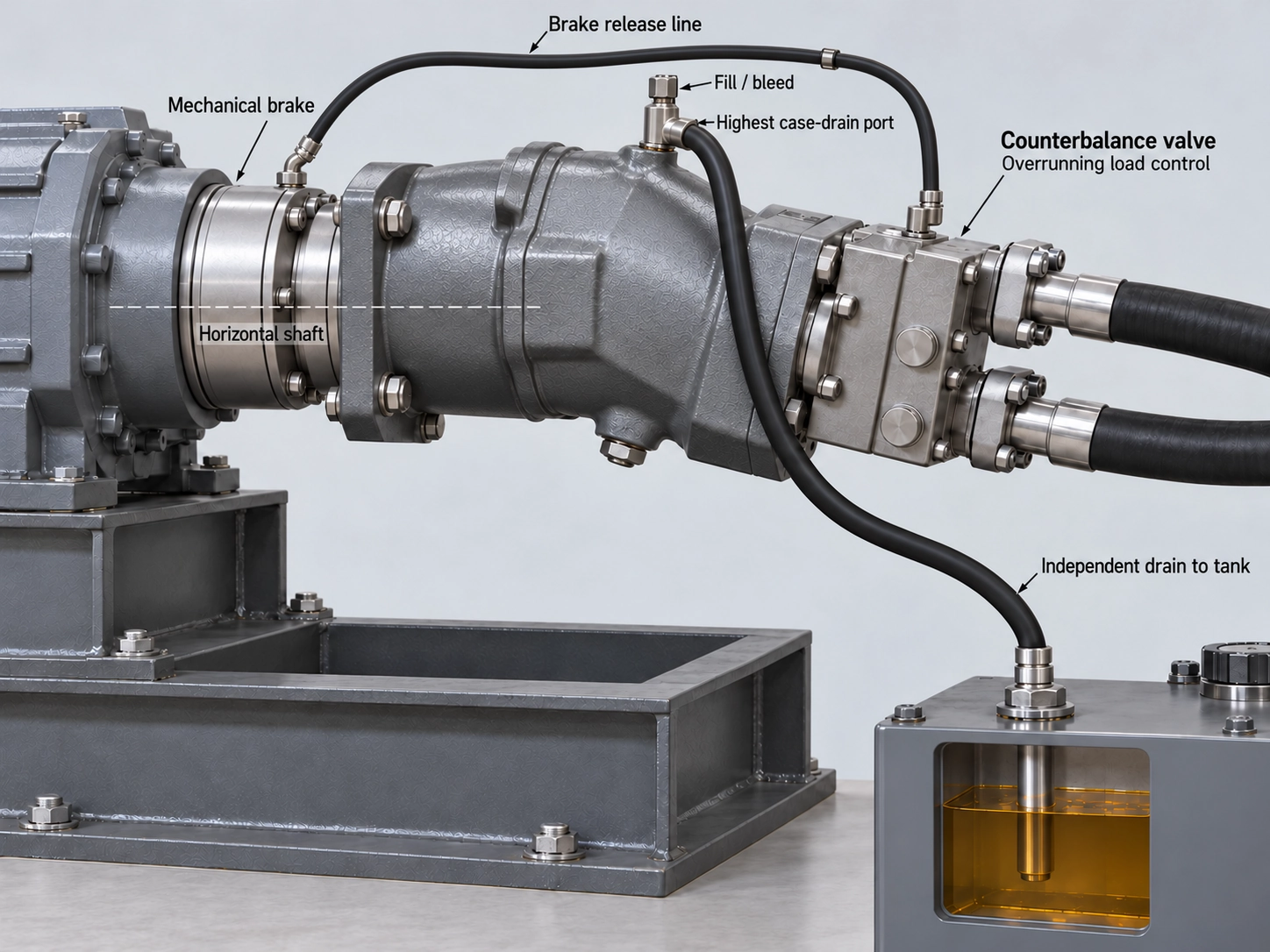
Motor selection, hydraulic load control, and mechanical braking are separate functions. The September 2007 manufacturer document discusses counterbalance control for overrunning operation and states that the counterbalance valve does not replace mechanical service or parking brakes.
The BVD/BVE examples in the September 2019 data sheet concern open circuits. Assess closed-circuit charge supply, low-pressure-side conditions, applicable flushing arrangements, and braking separately. Do not assume a counterbalance valve suits every installation.
Include these questions in the circuit review:
- How is speed controlled during lowering or deceleration?
- How are the required motor-port pressure conditions maintained?
- How is the mechanical brake released and applied?
- What happens when the drive command or hydraulic supply is removed?
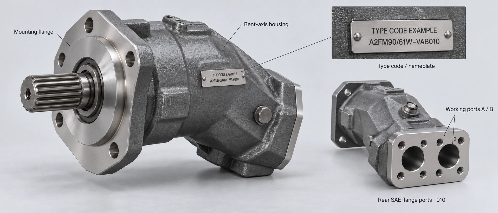
A photograph or displacement code cannot resolve these questions. Submit the circuit and brake sequence with the motor specification. Suspended-load and travel-braking functions require review of the complete machine system.
Confirm Installation and Fluid Conditions
Housing filling and case-drain routing
Provide an installation drawing showing shaft orientation, motor position relative to the reservoir, and proposed case-drain routing.
The Series 6 instruction manual addresses filling, air bleeding, and housing drainage. Its general guidance routes case-drain fluid through the highest case-drain port, with installation-specific provisions and exceptions: Bosch Rexroth RE 91001-01-B/08.2011, sections 7.2–7.3, third-party-hosted instruction manual.
Use the supplied unit's instructions to approve the installation, permissible case pressure, and commissioning procedure. A general selection article cannot establish the correct drain arrangement for every installation.
Fluid across the temperature range
Record the fluid designation, cold-start temperature, stabilized operating temperature, and available cleanliness information. Compare them with the selected motor's fluid and seal requirements.
The related guide to evaluating hydraulic oil viscosity at operating temperature explains the evaluation method in a piston-pump context. Its pump-specific limits are not A2FM motor specifications.
If temperatures are unknown, record them as unresolved inputs. Do not select a fluid grade from ambient temperature alone.
Verify the Exact Configuration and Supply Identity
Identify the manufacturer, complete type code, and applicable series before comparing performance or dimensions. Series 6, Series 6x, and Series 70 documents must not be treated as interchangeable specifications.
Check:
- Nominal size and exact geometric displacement.
- Shaft profile, engagement length, and coupling.
- Mounting flange, pilot, and fasteners.
- Working-port positions, connection details, and drain access.
- Seals, fitted valves, sensors, and other specified options.
- External shaft loads and their support arrangement.
The August 2011 instruction manual also calls for checking permissible radial shaft forces and indicates that a belt pulley may need separate support.
Matching displacement and appearance does not establish interchangeability. Resolve dimensional and configuration differences against approved drawings.
Sheungchak presents A2FM motor configurations for OEM and replacement inquiries. Bosch Rexroth documentation cited here describes Bosch Rexroth products; it does not certify a Sheungchak-supplied unit or establish an authorized distribution relationship. Confirm the manufacturer and supporting documents for the quoted motor.
Prepare an A2FM Application Review Request
A useful request connects the required machine behavior to a traceable motor configuration.
| Submission item | Information to provide |
|---|---|
| Driven function | Travel, lifting, lowering, or another defined task |
| Duty profile | Torque, speed, duration, frequency, starting, and reversal requirements |
| Hydraulic circuit | Open or closed circuit, available flow, working-port pressures, and fitted valves |
| Load control | Overrunning conditions, braking arrangement, and operating sequence |
| Installation | Orientation, reservoir relationship, drain routing, coupling, and shaft loads |
| Fluid conditions | Fluid designation, temperature range, and cleanliness information |
| Identification | Manufacturer, complete type code, nameplate photographs, and drawings |
| Acceptance requirements | Applicable limits, outstanding questions, and required verification |
For company information, see Guangdong Sheungchak Hydraulic Technology Co., Ltd.
For a configuration discussion, review the Sheungchak A2FM motor configuration page and submit the completed information through the Sheungchak technical inquiry contact page. Request the proposed motor's specification and drawing so its operating envelope and interfaces can be checked against your application.