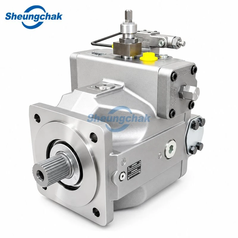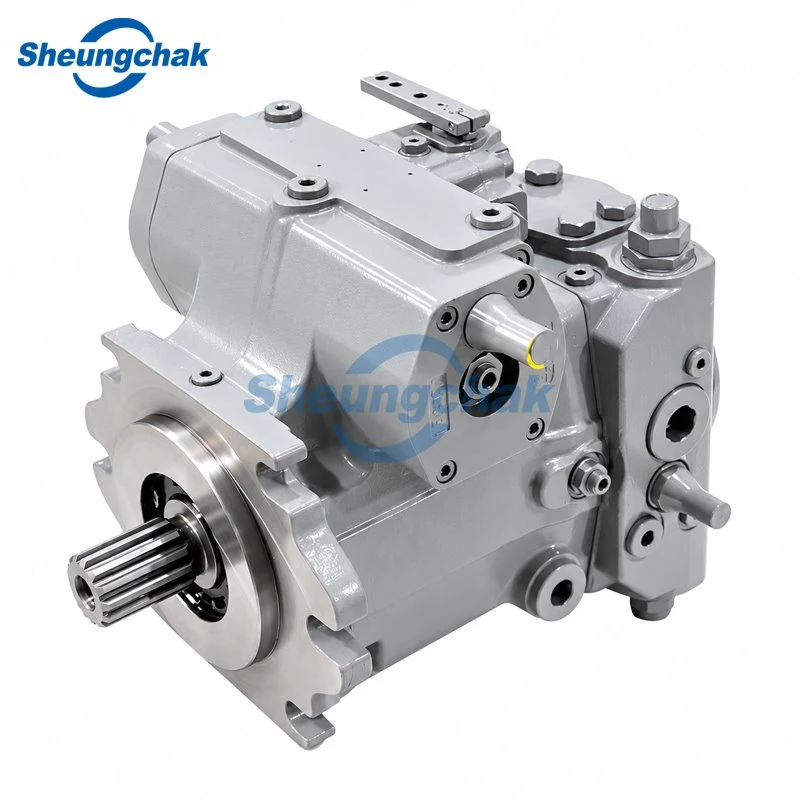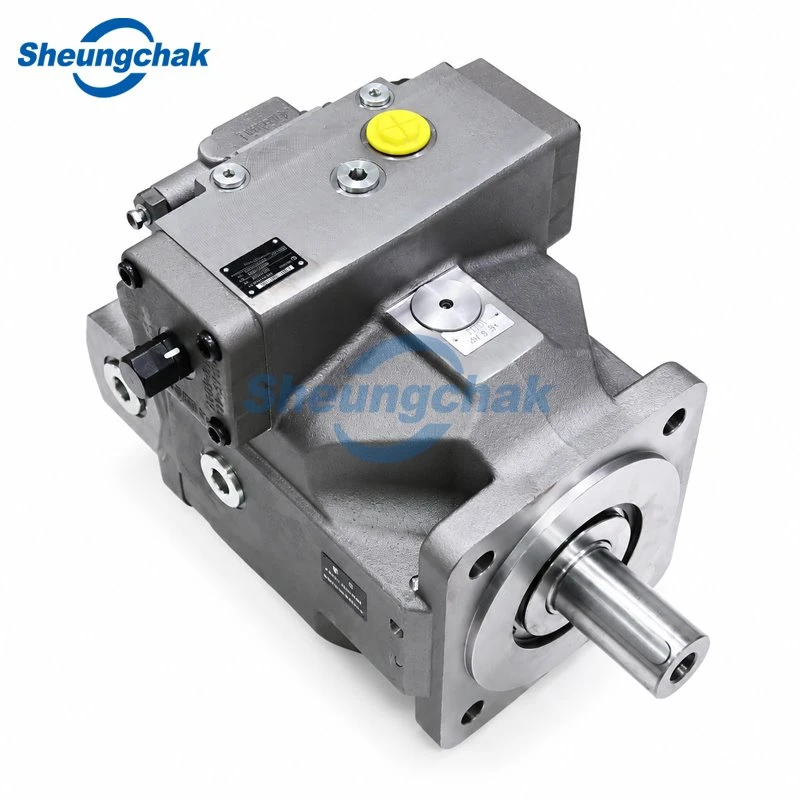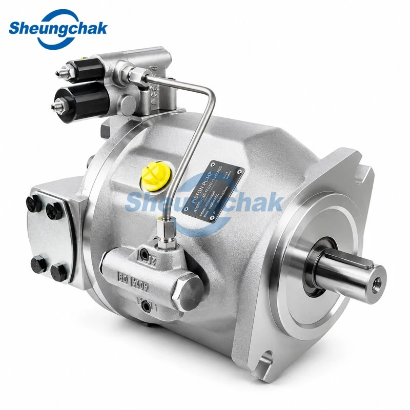

A4VG applications include hydrostatic travel drives and selected working drives in mobile machinery. Documented examples include road rollers, telehandlers, harvesting machinery and compact utility vehicles. However, a machine category alone does not establish compatibility: the pump must match the particular drive function, hydraulic circuit and control arrangement.
The useful starting question is therefore: what does the pump drive, and where does the main return flow go?
What Makes an Application Suitable for A4VG?
The A4VG is a variable displacement axial piston pump for closed-circuit hydrostatic drives. Main working flow circulates between the pump and a hydraulic motor, returning to the pump rather than passing through the reservoir first. Moving the swashplate through neutral reverses delivery direction. The working lines can exchange high-pressure and low-pressure roles as operating conditions change.
For an existing machine, review its hydraulic schematic in this order:
- Locate the driven function. Identify whether the pump serves travel, vibration, a feed drive or another task.
- Trace the two main working lines. Follow pump ports A and B to the motor or motor circuit and back to the pump.
- Identify the auxiliary paths separately. Mark the charge supply, case drains, control connections and any flushing arrangement. Reservoir connections in these auxiliary paths do not make the main working loop an open circuit.
- Record the duty and command signal. Establish the required speed range, loads, direction changes and control input before comparing pump configurations.
This is a document-review sequence, not an instruction to disconnect lines or test a running machine. Bosch Rexroth's A4VG Series 32 operating instructions, RE 92003-01-B, 2024-09-25, describe the pump and supporting circuits; the linked file is a third-party-hosted copy of the manufacturer's document.
For background on identifying the main oil path, see our open and closed circuit pump comparison.
A4VG Applications by Machine and Drive Function
| Machine category | Documented drive context | What to establish before selection |
|---|---|---|
| Road rollers | Closed-circuit road machinery drives | Whether the pump serves travel, vibration or another function |
| Telehandlers | Hydrostatic transmission using A4VG and A6VM components | The distinction between travel transmission and implement hydraulics |
| Harvesting machinery | Historical travel-drive and forage-harvester working-drive arrangements | The exact function, machine configuration and applicable documentation |
| Compact utility vehicles | Hydrostatic traction systems incorporating pumps, wheel motors and control valves | The complete drive layout and traction-control components |
Road Rollers

Bosch Rexroth's construction application material discusses closed circuits for road-roller travel and vibration drives and identifies A4VG/32 and A10VG/10 pumps in this context. It does not assign a particular pump to each function on every roller.
Locate the installed pump in the machine schematic and identify its driven motor. A request for a "roller hydraulic pump" leaves the travel-versus-vibration distinction unresolved.
Telehandlers

The same manufacturer material describes A4VG and A6VM drives for continuously variable power transmission in telehandlers. It separately refers to implement hydraulics and the travel drive.
Identify which circuit the requested pump serves. An A4VG transmission application does not establish that the pump supplies the boom-lifting cylinders. Both construction examples are documented on Bosch Rexroth's Construction and Infrastructure application page, which does not state a publication date.
Harvesting Machinery

Rexroth's Drive and Control Systems for Combine Harvesters and Forage Harvesters, RE 98071 from 2001, illustrates A4VG travel transmissions with fixed or variable displacement motors. It also shows an A4VG and A2FM arrangement associated with forage-harvester feed rollers.
These are historical design examples, not confirmation of current production-machine specifications. They show why a "harvester pump" inquiry should identify whether the task is propulsion or a separate working drive. See the Rexroth RE 98071 historical application brochure, 2001, hosted by a third party.
Compact Utility Vehicles

Rexroth's High-Efficiency Traction Control (HET) for Compact Vehicles technical paper describes a system combining A4VG or A10VG pumps, MCR wheel motors and a dedicated control block. Its examples include municipal vehicles, dumpers and farm loaders.
Traction control in that arrangement is a system function. Installing an A4VG pump alone does not establish the described HET functionality. The Bosch Rexroth HET technical paper is manufacturer material, rather than an independent performance comparison; its publication date is not established here.
Match the Series and Control to the Duty
The table below contains Bosch Rexroth reference specifications from the named editions. It is not a Sheungchak product specification or supply guarantee. It also does not describe every A4VG series, regional edition or currently available configuration.
| Reference document | Nominal size designations* | Nominal pressure | Maximum pressure |
|---|---|---|---|
| Series 32, RE-E 92003, 2021-08-11, Europe | 28–125 | 400 bar | 450 bar |
| Series 40, RE 92004, September 2017 | 110–280 | 450 bar | 500 bar |
*These are nominal size designations, not a substitute for exact geometric displacement data. Read the technical data for the selected size.
The source documents are Bosch Rexroth's Series 32 data sheet, RE-E 92003, 2021-08-11 and Series 40 data sheet, RE 92004, September 2017. Both linked copies are hosted by third parties.
Maximum pressure is not a continuous operating target. Check permissible pressure duration and the applicable speed, fluid and temperature conditions in the exact product documentation. The Series 40 figure of 500 bar does not establish that a proposed Sheungchak pump carries that rating; request the offered unit's own confirmed specification.
Control identification is equally important. The referenced Series 32 edition uses HD for hydraulic, pilot-pressure-related proportional control, while the Series 40 edition uses HP. Similar descriptions do not establish interchangeable hardware, signals or settings.
Record the complete control suffix and the machine's available command signal. Our A4VG control options and matching guide explains the identification checks in more detail.
Check the Complete Closed-Circuit System
The application review extends beyond the main working lines. Charge supply replenishes oil lost from the working loop and supports the relevant supply functions. Case drainage carries internal leakage oil out of the housing; its routing and pressure limits require a separate check.
Use the following table as a document-review worksheet. Record the document revision and any unresolved differences for the installed and proposed units.
| Review area | What to establish | Documents to compare |
|---|---|---|
| Charge supply and filtration | Integrated or external supply, required capacity, applicable pressure limits and filter arrangement | Exact pump data sheet, order configuration and machine schematic |
| Case drainage | Designated connections, drain routing, installation orientation and permissible case pressure | Installation drawing, operating instructions and machine schematic |
| Flushing and cooling | Where loop oil is exchanged, where heat is removed and how the arrangement relates to the duty | Machine schematic, flushing-component documentation and machine cooling specifications |
| Pressure protection | Specified relief and pressure cut-off configuration, including ordered settings | Order configuration, applicable data sheet and machine requirements |
| Motor and transmission | Motor identity, displacement arrangement and driven mechanism | Motor nameplate and data sheet, machine schematic and drivetrain documentation |
| Mechanical interfaces | Rotation, shaft, flange, working ports, installation space and through drive | Complete type code, installation drawing and machine mounting details |
The referenced Series 40 data sheet covers boost supply, filtration, installation and pressure limits. Its standard-version information must be checked against the ordered configuration. The Series 32 operating instructions likewise identify the installation drawing, data sheet and order confirmation as relevant documentation.
The HET paper provides one example of application-specific thermal management: its control block incorporates flushing with flow selected for the vehicle. It does not establish a universal flushing arrangement or setting for A4VG installations.
Have appropriately qualified personnel resolve configuration differences and follow the applicable machine manufacturer's procedures for installation and commissioning. Do not derive pressure settings or connection changes from this application overview.
Where A4VG Should Not Be Assumed to Fit
Apply these boundaries during selection:
- Machine name alone: a road roller or harvester still needs pump and drive-function identification.
- Valve-controlled lifting circuit: examine the working circuit before considering a closed-circuit transmission pump. A transmission application does not prove suitability for cylinder supply.
- Matching size or mounting dimensions: displacement and flange fit leave the control, pressure limits and auxiliary circuit unresolved.
- Different series or control version: treat substitution as a proposed engineering change until its operation, settings and interfaces have been reviewed.
Prepare an A4VG Application Review
Prepare the following information before requesting a configuration or replacement quotation:
- Complete pump identification: a readable nameplate photograph, full type code and material number where available.
- Machine identification: manufacturer, model and relevant configuration.
- Driven function: travel, vibration, feed drive or another identified task.
- Circuit information: machine schematic and connected motor details.
- Control requirements: complete suffix, command signal and electrical details where applicable.
- Operating duty: documented pressure, shaft speed, temperature and load cycle, with measurement conditions. Identify unknown values rather than estimating them.
- Interfaces and auxiliaries: shaft, flange, rotation, ports, charge supply and rear-mounted pumps.
For a supply inquiry, review the Sheungchak A4VG pump configurations and send the identification and application details above. Request written confirmation of the proposed series and full type code, control configuration, operating limits, mechanical interfaces, supporting circuit requirements and supply availability.