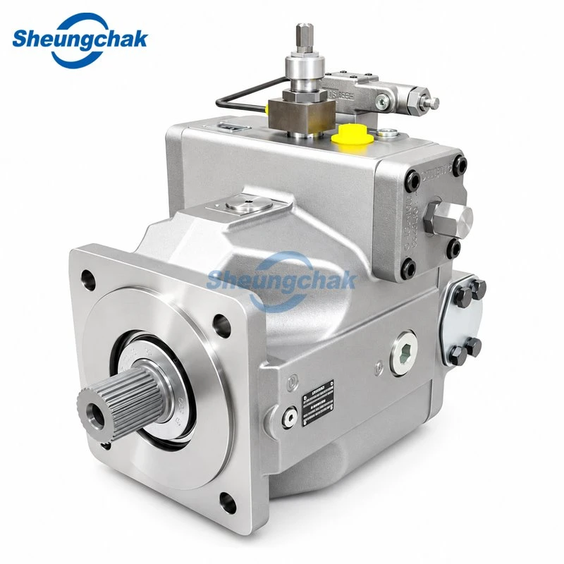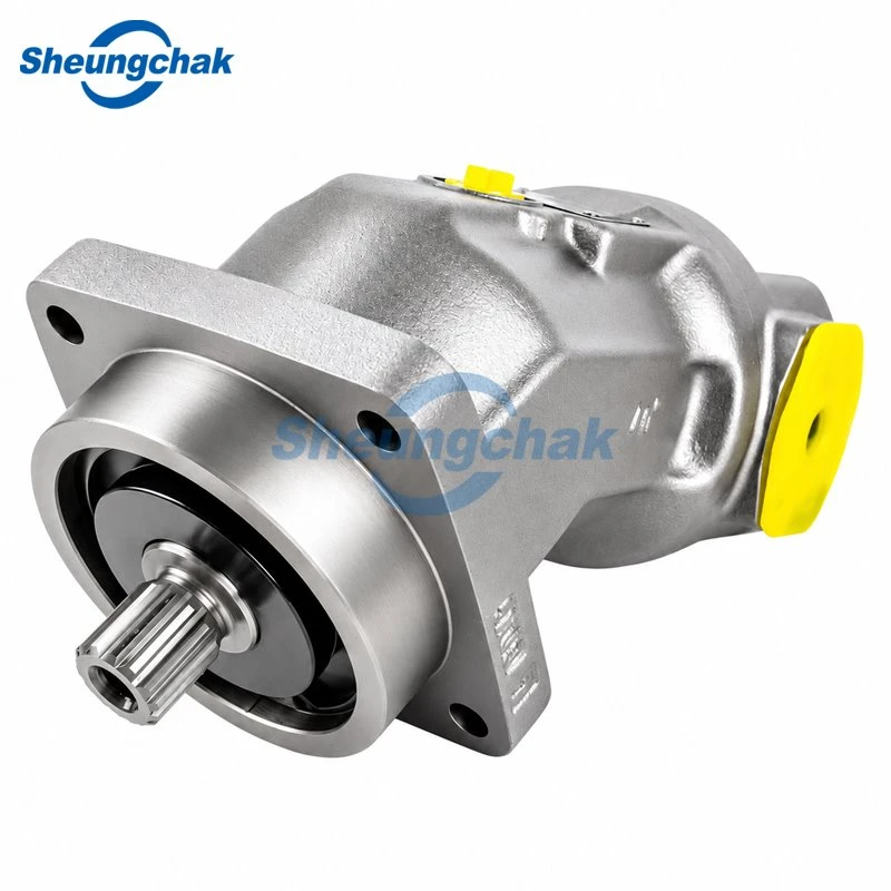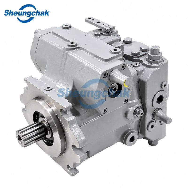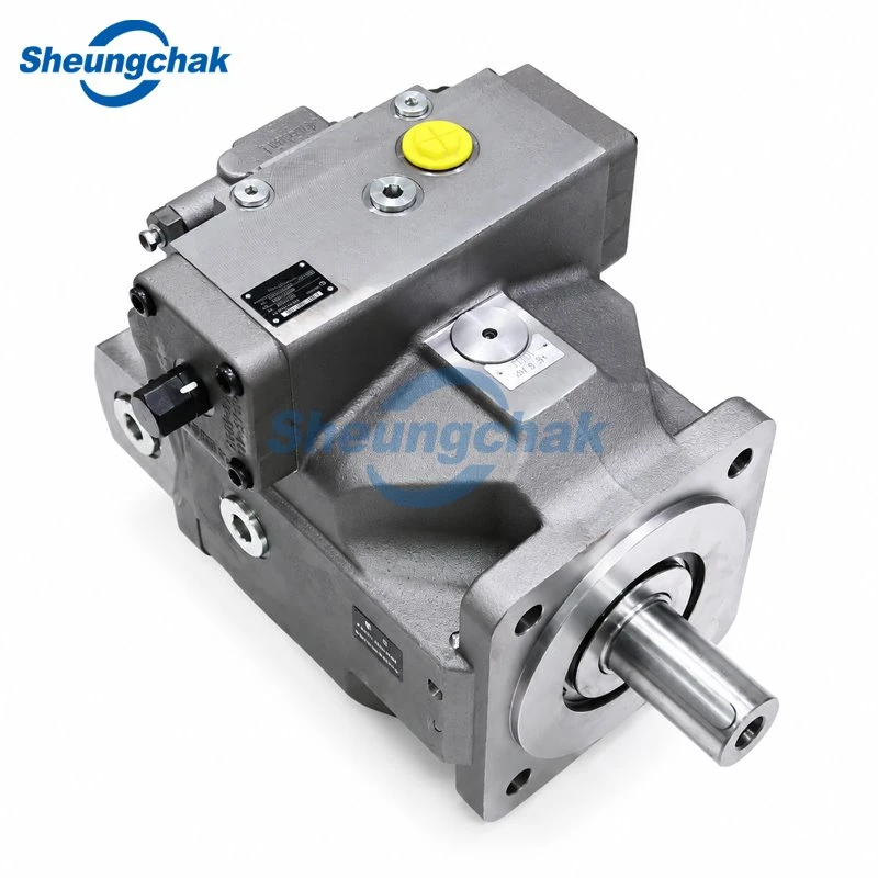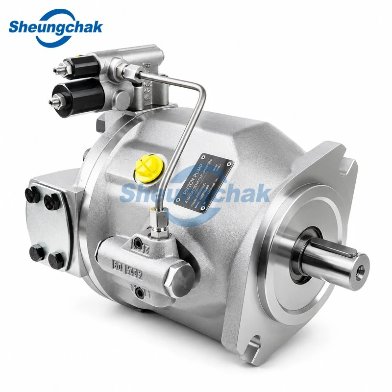

An A4VSO hydraulic press pump should be selected against the machine's complete pressure, flow, and time profile. Matching displacement alone leaves important questions unresolved: whether the pump can deliver the required flow at the available speed, how it will respond during pressing and holding, and whether its fluid and installation conditions are acceptable.
Start with the hydraulic schematic and a cycle worksheet. Use them to review pump size, control function, drive requirements, and installation as one configuration.

Where an A4VSO Pump Fits in a Hydraulic Press
Bosch Rexroth identifies the A4VSO as a variable-displacement axial piston pump for open circuits in RE 92050, dated June 15, 2023, a manufacturer document hosted by Rexton Hydraulic. That identifies its basic circuit type; it does not establish suitability for every press.
For application review, identify which cylinder movements the pump supplies and which depend on other circuit elements. A press with a prefill arrangement, for example, needs a different pump-flow assessment from one in which the pump supplies the full approach volume.
This guide uses original Bosch Rexroth documentation as reference material. Any proposed Sheungchak supply requires its own applicable specifications; the original manufacturer's ratings do not establish the performance of a proposed replacement.
Map Pressure and Flow Across the Press Cycle
Build a separate operating point for each stage. Record pressure and flow at the pump, stage duration, and the valve or control state. Avoid combining the highest pressure from one stage with the highest flow from another unless that combination actually occurs.
Before filling in the flow column:
- Identify the cylinder chamber being supplied and its effective area for that movement.
- Establish the required ram speed and corresponding cylinder inflow from effective area multiplied by speed, using consistent units.
- Trace the actual supply path through the schematic, including prefill valves, regeneration, accumulators, and auxiliary pumps.
- Determine the main pump's contribution, including relevant leakage and control-flow demand, rather than entering cylinder inflow as main-pump flow automatically.
Use the worksheet below for machine data. The empty fields are a reusable recording template, not measured machine data; complete them through measurement or engineering confirmation.
| Cycle stage | Pump pressure, bar | Pump flow, L/min | Duration, s | Valve and control state |
|---|---|---|---|---|
| Approach | ||||
| Pressing | ||||
| Holding | ||||
| Decompression, if used | ||||
| Return | ||||
| Idle or unloading |

Approach
Identify the required cylinder speed and how the cylinder receives fluid. Check the schematic for prefill valves, regeneration, accumulators, or auxiliary pumps before translating cylinder movement into main-pump demand.
Include the transition into pressing. A pump that meets the steady approach requirement still needs an appropriate control response when the operating state changes.
Pressing and Holding
Record forming pressure and flow together. For holding, identify whether the pump actively maintains pressure or whether the circuit isolates the cylinder and requires only intermittent replenishment. Do not enter zero pump flow solely because the ram is stationary.
Separate sustained working pressure from short-duration maximum pressure. RE 92050/2023-06-15 specifies the following reference ratings:
| Documented configuration | Nominal pressure | Maximum pressure |
|---|---|---|
| Port plates 13 and 25 | 350 bar | 400 bar |
| NG 370 with port plate 36 and specified eligible control devices, as listed in the 2023 type code | 380 bar | 420 bar |
Its working-pressure table applies to mineral-oil-based fluids. Maximum-pressure operation is limited to a single operating period of 1 second, a total of 300 hours, and approximately one million cycles. These limits apply together; maximum pressure is not an unrestricted continuous rating. Check the complete type code, fluid, and operating conditions against the applicable working-pressure table on page 8.
For port plate 36, also check the controller-dependent minimum working pressure specified in the type-code notes on page 3.
These reference values must not be assigned to an aftermarket pump without its manufacturer's written confirmation.
Return
Determine the effective cylinder area and the actual return-flow path. Review decompression separately where the machine uses it, rather than assuming the pump controller alone handles pressure release.
The completed worksheet should show which stage determines flow, which determines sustained pressure, and which transitions need closer control review.
Check Pump Size, Speed and Drive Power
Use the following relationships for preliminary assessment:
Q = Vg × n × ηv / 1000
Pshaft = Δp × Q / (600 × ηt)
Here Q is delivered flow in L/min, Vg is operating displacement in cm³/rev, n is pump speed in rpm, Δp is pump outlet pressure minus inlet pressure in bar, using the same pressure reference, ηv is volumetric efficiency, and ηt is total pump efficiency. Use efficiencies applicable to the configuration, pressure, speed, and fluid conditions being assessed. Pshaft is expressed in kW. The relationships appear in RE 92050, page 11.
Screen candidate configurations in this order:
- Establish actual pump flow for each stage. Use the completed cycle worksheet and the circuit's supply arrangement.
- Identify available pump speed. Use the actual drive arrangement and operating speed, including any variable-speed conditions.
- Estimate required displacement. Rearrange the flow equation as Vg = 1000 × Q / (n × ηv). Obtain efficiency inputs for the relevant operating point.
- Check the candidate's operating envelope. Compare required displacement, speed, pressure, and inlet conditions with the proposed configuration's documentation.
- Calculate shaft demand at simultaneous pressure-and-flow points. Evaluate the operating combinations that actually occur.
- Review the drive and the resulting cycle time. Check motor torque capability, starting conditions, overload allowance, thermal duty, and any auxiliary-pump loads with the drive supplier.
Do not substitute an unexplained assumed efficiency and present the result as a confirmed selection. Pump shaft power and electrical input power are different quantities.
If a power-limiting controller reduces displacement under load, check whether the remaining flow still achieves the required pressing speed. A power limit can protect the drive while making a proposed cycle time unattainable.
These calculations screen candidates. Final selection requires the proposed pump's operating envelope and the drive's applicable ratings.
Match the Control Function to the Press Circuit
Define the required behavior before choosing a control code.
| Required behavior | Question to resolve | Decision for application review |
|---|---|---|
| Pressure regulation | What pressure command, adjustment range, and transition response does the process require? | If the pump maintains holding pressure, review pressure regulation together with replenishment demand; cylinder load holding requires a separate circuit review. |
| Flow regulation | How is the flow demand generated, and which sensing or pilot connections are needed? | If stage flow demand changes, establish how the circuit commands pump delivery and verify the required sensing or pilot arrangement. |
| Power limitation | What drive limit applies, and what happens to machine speed when it is reached? | If a duty point exceeds the drive allowance, review power limitation and recalculate the resulting ram speed and cycle time. |
| Electronic control | Which command signals, feedback devices, electronics, and commissioning settings must match? | If the press uses electronic commands or feedback, verify the complete pump, electronics, signal, and sensor combination. |
Bosch Rexroth RE 92060, edition January 2017, hosted on a third-party website, separately documents DR pressure control, DP pressure control for parallel operation, FR flow control, and DFR pressure-flow control. Its ordering table shows configuration-dependent availability.
Electronic options require their own documentation. Bosch Rexroth's official A4V HS5(E) product information describes swivel-angle, pressure, and torque control for that system. These functions should not be assumed for every A4VSO configuration.
Review the controller together with the press valves and sequencing. Pressure regulation should not be treated as proof of cylinder load holding, controlled decompression, or machine safety functionality.

Verify Fluid, Inlet and Case Drain Conditions
Prepare a fluid-and-installation record alongside the cycle worksheet. Include the fluid product name, viscosity grade, cold-start temperature, stabilized operating temperature, reservoir level, and proposed mounting position.
Compare the fluid's properties at those temperatures with the selected pump's requirements.
For inlet review, request the permissible inlet conditions at the intended speed and displacement. Assess the complete suction path, including restrictions under cold-start conditions. If the machine already shows noise or unstable delivery, the guide to hydraulic pump cavitation and inlet checks provides a focused troubleshooting path.
For the documented mineral-oil configurations without a charge pump, RE 92050 lists a minimum inlet pressure of 0.8 bar absolute, subject to the speed-displacement limits. Its static case-pressure ceiling is 4 bar absolute, with case pressure no more than 1.2 bar above inlet pressure and further restrictions from the case-pressure curve. Check these conditions together in pages 7–9; they are reference limits for the documented units, not ratings for an unverified replacement.
For the case drain, verify the selected port, line routing, and allowable backpressure. RE 92050 requires filling and air bleeding and specifies drainage through the highest applicable drain port for the installation position. Use its installation instructions on pages 75–77 for the documented configurations.
Treat filtration and cleanliness as separate checks. Ask for a documented cleanliness target and a sampling method; a filter's micron label alone does not establish the condition of the operating fluid. The guide to hydraulic pump filtration and cleanliness verification explains the checks involved.
HFC service needs a specific review. Bosch Rexroth RE 92053, edition November 2018, hosted by Hydba, covers dedicated HFC configurations. It requires external bearing flushing for the F variant, while the F2 variant operates without external bearing flushing subject to its installation conditions. F2 size availability must also be checked against the applicable ordering code; it is not an unrestricted option for every size. Fluid-dependent operating requirements still apply. A seal change alone does not demonstrate an approved conversion.
Review Replacement and Installation Compatibility
For an existing press, compare the original and proposed configurations field by field.
| Item | Evidence to request |
|---|---|
| Complete identity | Readable nameplate and full type code, including suffixes |
| Rotation and shaft | Specified viewing direction, shaft drawing, and coupling details |
| Mounting | Flange drawing, pilot dimensions, fastening pattern, and installation space |
| Hydraulic connections | Port functions, connection sizes, orientation, and pressure ratings |
| Controls | Functional diagram, settings, pilot connections, and electrical interfaces |
| Through drive, if fitted | Connection details and permissible transmitted loads |
| Operating conditions | Approved pressure, speed, fluid, temperature, and drain conditions |

Use photographs to explain the installation, supported by drawings and specifications. Physical fit alone does not confirm equivalent control behavior.
Record unresolved differences and who must approve them. If shaft, flange, rotation, port function, or control interfaces differ, compare the applicable drawings and functional diagrams, obtain an approved modification plan where needed, and withhold a direct-interchangeability conclusion until the differences are resolved. Plan commissioning checks around the actual press cycle, including transitions, holding behavior, inlet conditions, and case pressure. Do not describe a replacement as directly interchangeable while these items remain open.
Information to Prepare for an A4VSO Pump Review
Prepare the following information for a supplier review:
- Original nameplate and complete model code, or the proposed new-system specification.
- Hydraulic schematic and completed pressure-flow-time worksheet.
- Required ram speeds, holding behavior, and transition requirements.
- Motor rating, pump speed, drive arrangement, and any auxiliary-pump loads.
- Fluid identity, temperature range, and available cleanliness records.
- Installation photographs, interface drawings, reservoir arrangement, and drain routing.
- Existing control signals, feedback devices, and known operating problems.
For a Sheungchak application enquiry, use the A4VSO hydraulic pump configurations page and include this review package. Request a configuration-specific response identifying the proposed model, applicable ratings, interface compatibility, installation requirements, and any unresolved differences before approving the pump for the press.