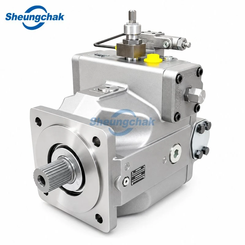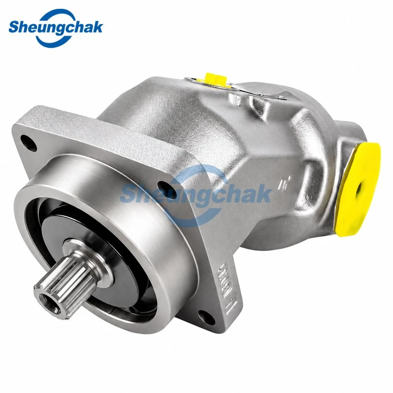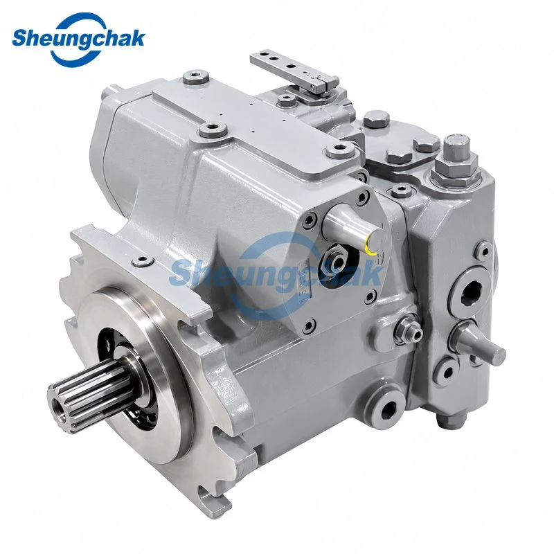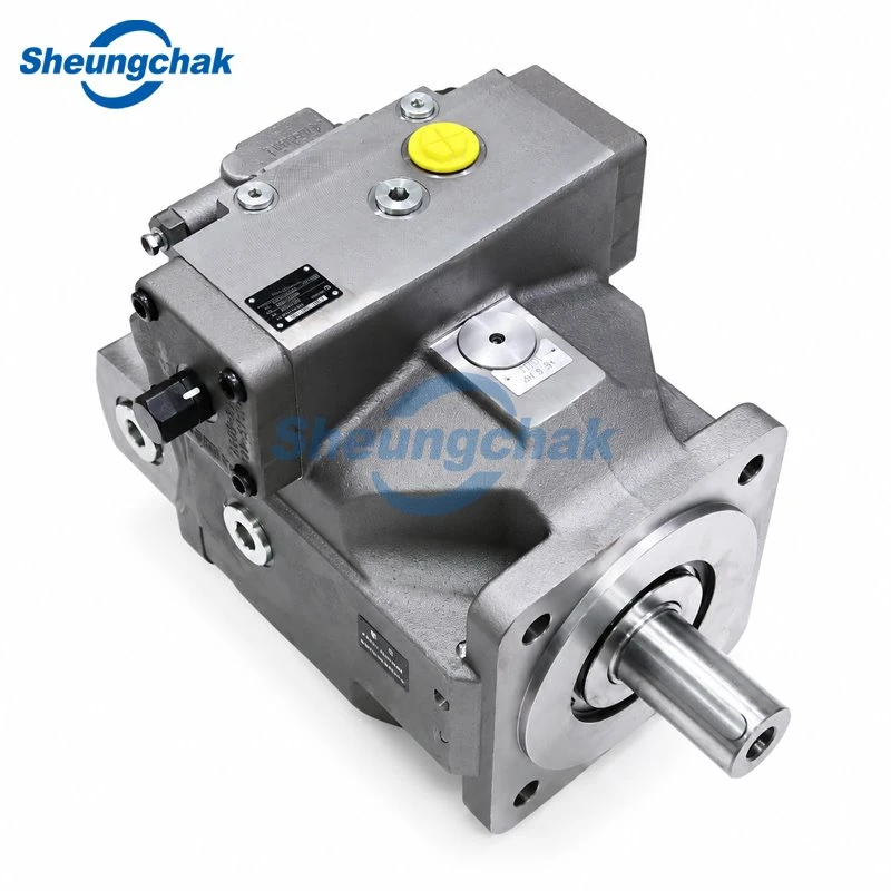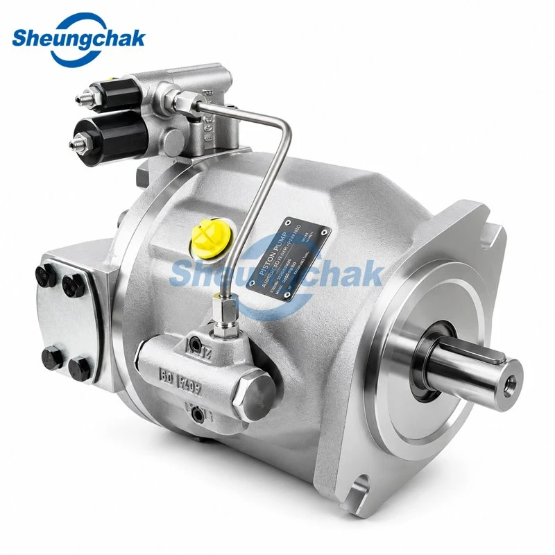

A replacement hydraulic pump for an excavator needs to match the machine's identity, operating requirements, control system and physical interfaces. A familiar model name or a similar-looking housing is only a starting point.
Begin with the machine serial number, OEM assembly part number and complete pump code. Then compare flow under equivalent conditions, separate pump pressure ratings from machine settings, and verify the regulator, drive connection and ports. Keep unresolved differences visible until supporting documents or a technical review settle them.
This guide covers replacement matching for an existing excavator main pump. It does not provide universal pressure settings, regulator adjustment instructions or an interchange list.
Start with the Machine and the Complete Pump Identity
The machine model, OEM part number and pump manufacturer's code identify different things. Record all three rather than treating them as interchangeable references.
Bobcat's official page for excavator pump 7349884 provides a compatibility check using the machine serial number or model. This supports beginning identification with machine-specific parts information rather than assuming a model name establishes fitment. (Bobcat Company)
Machine Serial Number, OEM Part Number and Pump Code
Build an identification record before comparing quotations.
| Identification field | What to collect | What it helps establish |
|---|---|---|
| Machine identity | Manufacturer, full model and serial number | The relevant machine configuration and parts information |
| OEM assembly part number | Number from the applicable parts record, including any documented replacement number | Which complete assembly the machine requires |
| Pump identity | Manufacturer, complete model code and serial number | The installed unit's stated configuration |
| Regulator identity | Complete regulator code, revision and any separate identification plate | The control assembly that needs verification |
| Installation evidence | Overall photographs and clear views of the shaft, flange, ports and controls | Whether documents correspond to the installed hardware |
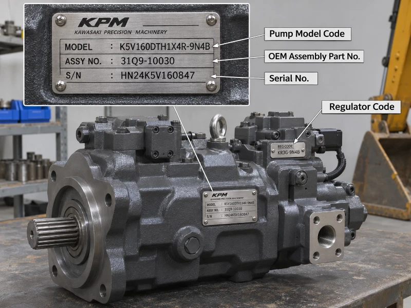
Copy every character, including suffixes and revision identifiers. Photograph the plate as well as transcribing it so the supplier can check uncertain characters.
For the detailed identification process, see how to identify a hydraulic pump from its nameplate.
If the plate is missing, a housing photograph may help narrow the search, but it should not become the sole basis for ordering. Use the machine parts record, any documented replacement history and dimensional evidence to resolve the identity. If those sources disagree, keep the request open for technical review.
Match Flow Using the Same Measurement Basis
A flow value becomes useful only when its scope and operating conditions are clear. Before comparing two figures, establish whether each describes one pump section, a complete assembly or the machine's main hydraulic system.
Per-Section Flow vs Combined System Flow
Caterpillar's UK-region 320 product page, accessed November 3, 2026, lists 429 L/min as the main system maximum flow. The page label does not identify that figure as the output of one pump section. Do not assign it to a single section or divide it equally between sections without supporting machine documentation. (Caterpillar)
Use a comparison record that preserves the meaning of each number:
| Value | Measurement basis | Conditions or limitations | Source |
|---|---|---|---|
| 429 L/min | Cat 320 main system maximum flow | Referenced regional product configuration; not a per-section test result | Caterpillar product specifications |
| Candidate pump flow | Identify each section and measurement point | Record shaft speed, pressure, displacement command and oil conditions | Applicable specification or identified-unit test report |
| Existing machine flow | Identify the circuit and measurement point | Record machine mode and simultaneous measurements | Machine-specific service test record |
| Calculated flow | Theoretical displacement-based value | State assumed displacement and shaft speed; excludes volumetric losses | Transparent calculation |
A quotation stating only "flow matches original" leaves the comparison incomplete. Ask which original specification it matches and under what conditions.
Speed, Displacement and Test Conditions
For a pump section, theoretical flow can be calculated as:
Qtheoretical = Vg × n ÷ 1000
where Q is in L/min, Vg is the geometric displacement at the stated setting in cm³/rev, and n is shaft speed in rpm.
Illustrative calculation-not a product specification: a section operating at an assumed displacement of 100 cm³/rev and 1,800 rpm has a theoretical flow of 180 L/min. This calculation does not establish its measured delivery at working pressure.
For a variable-displacement unit, record the displacement command or control condition as well as speed. A comparison between maximum theoretical delivery and a measured, partially destroked operating point does not show whether the pumps are equivalent.
Also verify displacement against the applicable documentation. Kawasaki's online K3V/K5V specification table, accessed November 3, 2026, lists 117 cm³ in the K3V112 column. Its KPM1410 catalogue, dated October 2014, identifies 112 cm³ for that size.
The documents establish a discrepancy; they do not explain which value applies to a particular installed or offered unit. Do not resolve it by assuming the model digits are a complete specification. (Kawasaki product page; Kawasaki KPM1410, October 2014)
Separate Pump Pressure Ratings from Machine Settings
Record pump ratings and machine pressure settings in separate fields. They describe different limits and cannot substitute for one another.
| Pressure field | What to establish | Evidence to request |
|---|---|---|
| Pump rated pressure | The manufacturer's rating and its stated operating conditions | Applicable pump documentation |
| Pump peak pressure | Permitted transient conditions and restrictions | Applicable pump documentation |
| Machine circuit maximum | The relevant circuit, mode and machine configuration | Machine specifications or service information |
| Relief or control setting | The specified adjustment and verification procedure | Machine-specific service instructions |
| Measured operating pressure | Measurement location and operating condition | Recorded diagnostic test |
For example, the referenced Cat 320 page distinguishes equipment maximum pressure of 35,000 kPa from equipment lift-mode maximum pressure of 38,000 kPa. These are machine specification categories, not instructions to adjust a replacement pump. (Caterpillar)
A higher advertised pump pressure rating does not, by itself, demonstrate compatibility or authorize a higher machine setting. Verify the replacement against the applicable operating envelope and the machine's control requirements.
Likewise, a low pressure reading during a machine test is diagnostic evidence, not a complete replacement specification. Retain the test procedure, measurement point and operating conditions so the result can be interpreted correctly.
Check the Pressure–Flow Operating Point and Power Limit
Pressure and flow must be evaluated together at the same operating point. Two separate catalogue maxima do not establish that both are available simultaneously or continuously.
The hydraulic power relationship, expressed in SI units, is:
Ph = Δp × Q ÷ 600
where Ph is hydraulic power in kW, Δp is the pressure difference in bar and Q is flow in L/min. The Lee Company's engineering reference presents the equivalent pressure-drop–flow relationship in US customary units. (The Lee Company)
Teaching example-all inputs are assumptions:
- One section delivers 180 L/min across a pressure difference of 250 bar.
- Hydraulic output is 250 × 180 ÷ 600 = 75 kW.
- At an assumed overall pump efficiency of 0.90, shaft input would be approximately 75 ÷ 0.90 = 83.3 kW.
If two sections simultaneously operated at those assumed conditions, their combined hydraulic output would be 150 kW and the combined pump shaft input approximately 166.7 kW. Other driven loads would require separate consideration.
These figures are not a recommended setting or the performance of a named excavator. They show why a replacement review needs the simultaneous pressure–flow requirement and the available drive-power allocation.
Ask for the applicable control curve or test evidence across the required operating range. A single maximum-flow figure cannot establish the unit's response as pressure rises.
Match the Regulator and Control Configuration
Treat regulator compatibility as a separate acceptance item. Matching the pump family and pressure rating does not complete the control review.
Kawasaki's October 2014 KPM1410 catalogue distinguishes regulator codes and design codes, and lists control combinations involving negative flow control, positive flow control, load sensing and horsepower control. These are configuration choices; the catalogue should not be read as saying every option applies to every unit. (Kawasaki KPM1410 catalogue)
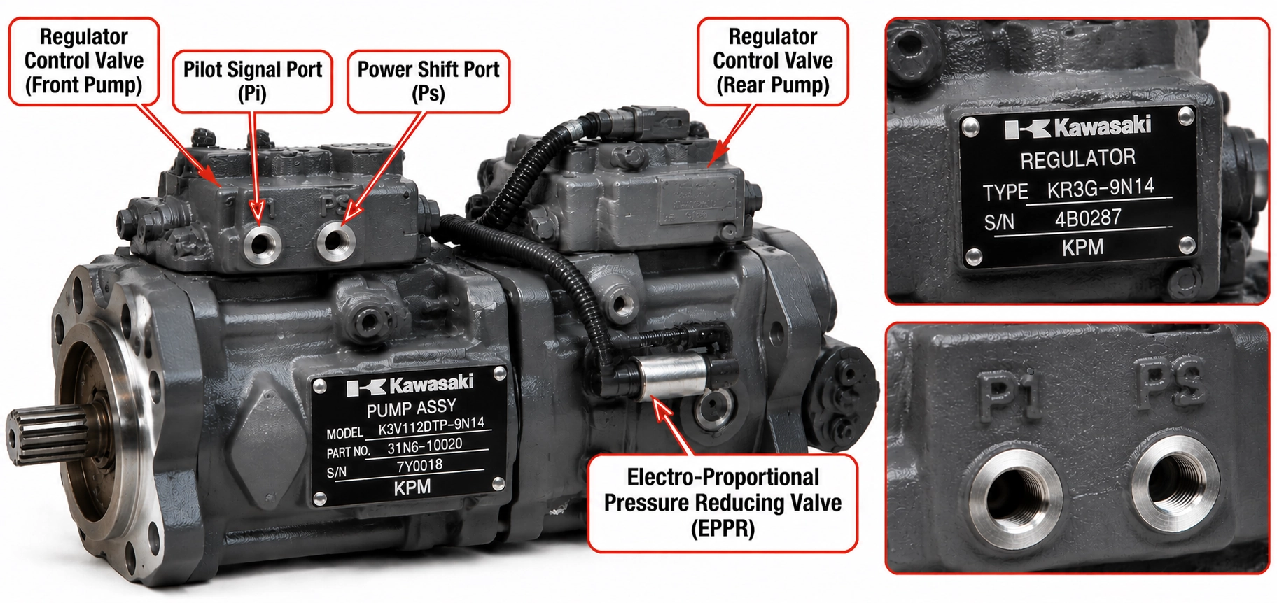
Control Type, Signals and Settings
Use the following as a review worksheet, with the applicable machine and pump documents providing the actual requirements.
| Control item | Question to resolve |
|---|---|
| Regulator identification | Do the complete code and revision match the approved configuration? |
| Control architecture | Does the proposed assembly support the machine's documented control method? |
| Hydraulic signals | Are signal functions, pressure ranges and port assignments compatible? |
| Electrical equipment, where fitted | Are the component identity, connector, pinout and command characteristics documented? |
| Power or torque control | Does the control characteristic suit the machine's drive-power allocation? |
| Multiple-section coordination | Are any required companion-pressure or combined-control functions retained? |
| Calibration | What settings and verification results apply to the offered assembly? |
Do not infer interchangeability from matching connectors or from a regulator that physically bolts onto the housing. Resolve the signal functions and control characteristics before acceptance.
For a K3V112-related identification task, the K3V112 configuration and regulator identification guide explains which code information to preserve. It does not establish that all K3V112 assemblies are interchangeable.
Verify the Shaft, Flange, Rotation and Ports
Compare the proposed assembly with an approved drawing and the installed configuration. Photographs help identify differences; dimensions and component specifications are needed to settle them.
Kawasaki's referenced dimensional material defines rotation from the shaft-end viewpoint. Preserve that viewpoint when recording clockwise or counterclockwise rotation so two descriptions are genuinely comparable. (Kawasaki KPM1410 catalogue)
The interface review should cover:
Drive shaft
Spline or key specification, dimensions, engagement and coupling compatibility.
Mounting flange
Pilot diameter, mounting pattern, register and installed position.
Rotation
Required direction and the stated observation point.
Suction or inlet port
Location, connection dimensions, connection standard, sealing arrangement and compatibility with the existing suction line.
Main delivery ports
Identify the outlet for each pump section and compare its location, orientation, connection standard, sealing arrangement and dimensions.
Pilot or control ports, where fitted
Identify each function and verify the connection against the applicable hydraulic schematic.
Case-drain ports
Confirm the approved port arrangement, routing and applicable case-pressure requirements.
Overall envelope
Clearance for the housing, regulator, fittings and connected lines.
Attached equipment
Any pilot pump, auxiliary stage or through-drive arrangement included in the assembly.
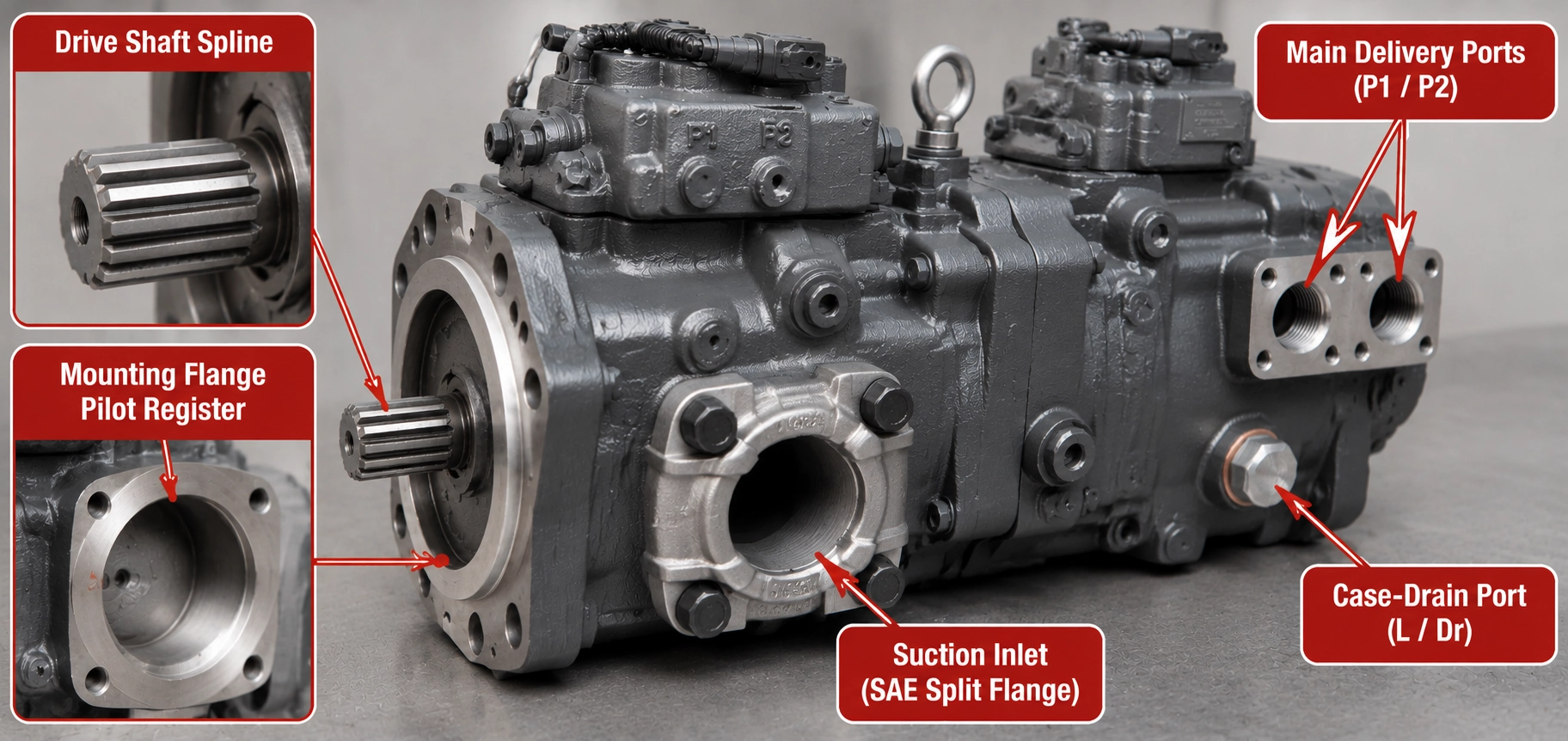
Photograph each port group and its markings. Use the drawing and schematic for the exact assembly to establish port functions rather than assigning them from appearance alone.
The K3V112 replacement pump product reference is a commercial product page. Its published 112 cc/rev per-section figure does not resolve the official documentation discrepancy discussed above. Request documentation tied to the complete offered model before using that figure for matching.
A documented like-for-like replacement and an assembly with changed interfaces require different decisions. Where drawings and identification records agree, continue to performance and control verification. Where a shaft, port or regulator differs, pause acceptance until the proposed change has a documented engineering basis.
A hose adapter or transferred regulator may address one visible difference without resolving the complete installation. Do not approve the assembly merely because it can be connected.
Review Test Evidence Before Accepting a Replacement
Ask what was tested, under which conditions and against which acceptance criteria. A report becomes useful when it is traceable to the offered unit and relevant to the machine requirement.
A supplier test report documents tests on the offered pump assembly. A machine service test record documents the existing machine's hydraulic operating condition. Keep both where available: they answer different questions, and neither replaces the other.
The following is a proposed buyer's evidence checklist, not a claim that every supplier performs these tests.
| Evidence field | What a useful record should identify |
|---|---|
| Tested assembly | Complete pump and regulator identification, plus serial number or another traceable unit reference |
| Test conditions | Fluid, temperature or viscosity basis, shaft speed and inlet conditions |
| Delivery measurements | Flow and pressure measured together, with each section identified where relevant |
| Control response | Commands or signal conditions and the corresponding measured response |
| Case conditions | Drain-flow measurement point, case pressure and relevant operating conditions |
| Acceptance basis | Applicable specification, agreed limits and pass/fail results |
| Test traceability | Date, responsible party, method and instrument identification or calibration status |
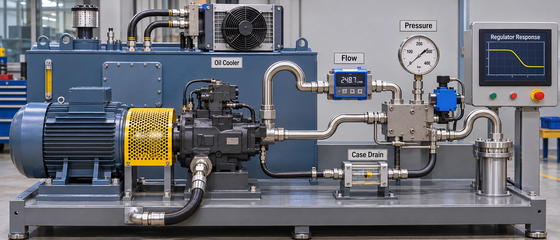
A low-pressure flow result alone does not establish delivery at the required working pressure. A report stating "pressure passed" also needs enough information to explain what condition was tested.
For case-drain evidence, distinguish the pump housing measurement from flows collected elsewhere in the installation. Do not apply an unexplained leakage threshold to every pump. The guide to interpreting hydraulic pump case-drain test results provides a separate diagnostic reference.
Keep product condition and brand relationship explicit in the quotation. New aftermarket, original and remanufactured descriptions should be supported by the supplied documentation. The guide to comparing original and aftermarket pump evidence addresses that procurement distinction.
Installation and commissioning remain machine-specific tasks. Qualified personnel should follow the applicable service instructions. This matching checklist does not authorize pressure adjustments or substitute for commissioning procedures.
Prepare a Complete Pump-Matching Request
Send a matching package that allows the supplier to identify the assembly, document differences and explain the basis of its proposed replacement.
Include:
- 1Machine manufacturer, complete model and serial number.
- 2OEM assembly part number and any documented supersession.
- 3Clear photographs of the complete pump and regulator identification.
- 4Shaft, flange, suction, delivery, control and drain-port photographs or drawings, plus installed-clearance information.
- 5Machine hydraulic and electrical references relevant to pump control.
- 6Available operating measurements, including the conditions under which they were taken.
- 7Required product condition and the evidence expected with the quotation.
Ask the supplier to return the complete proposed model, regulator configuration, supporting drawings, applicable operating limits and a written list of any deviations.
Close the review with one of three recorded outcomes:
Matching confirmation does not replace installation and commissioning acceptance.
Next step: Use the replacement pump inquiry form to enter your name and email address in the corresponding fields. Include the machine identifiers, complete pump and regulator codes, and available operating data in the Content field. Send photographs and drawings to the email address listed on that page. Request a documented comparison identifying confirmed matches, outstanding information and any proposed deviations.